
In the last post, I was able to get the μController version of the display module working with a basic test routine that proved that 1. the controller could be programmed and 2. the display was being driven correctly. The next stage is to flesh this out to replicate the MAX2771 API. The purpose here is not to simply create a duplicate of the MAX2771 which does a great job on its own. This approach means that I can re-use the code I created for the MAX2771 display module project. The additional goal of this small project was to gain experience in creating a SPI slave! Interfacing with the MAX2771 was simple since that is already a SPI slave unit. All I needed was to just create the master.
Connecting things together
I still have things set up from the previous tests so it was just a matter of connecting things back up again. Though this time I had two units to program instead of just one. I still have the main controller board for the clock to complete so I used the myAVR Dev board as a provisional main controller. Luckly, the myAVR dev board comes with its own programmer. I had to program this via the myAVR ProgTool since the BASCOM-AVR IDE was in use with programming the display module via the AVRISP mkII. It sounds more awkward than what it turned out to be. The part that was awkward was that the AVRISP mkII had trouble programming the display module while the SPI connection was still made to the myAVR dev board (my provisional mainboard). I had to disconnect the /SS, MOSI and CLK from the display module before being able to program. This would be a point of research to work out what is involved to be able to program the display module while still connected!
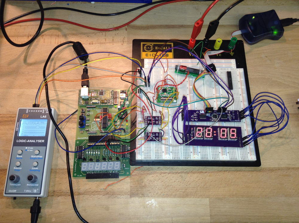
Once the infrastructure of programmers and connections was sorted, it was just then a matter of piecing together the code to enable the slave unit to start servicing the requests of the master i.e to start displaying the time. With the Real Time Clock still connected (via an I2C bus) I had a neat source of test data.
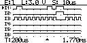
Getting thing up and running was rewarded with a red blinking LED on the dev board. This was my signal that the communication with the Real Time Clock was functioning. The next was the display module itself.To keep things simple, I am opting to use the basic BASCOM constructs for SPI. The logic analyzer was useful for seeing that the SPI messages were being sent. Though my particular logic analyzer only shows that there was activity. It lacks the sophistication of being able to see exactly what was being sent. Thankfully, I have been able to get things working without that level of sophistication.
Creating the Slave
Dim Rbit As Bit
Config Pinb.4 = Output                    ' MISO
Config Spi = Hard , Interrupt = On , Data Order = Msb ,
       Master = No , Polarity = Low , Phase = 0 , Clockrate = 128
Spiinit

On Spi Spi_isr Nosave

Enable Timer0
Enable Timer1
Enable Interrupts
The snippet above shows how the slave was defined. Basically I used the same construct in the master. The “Master = yes” property is the only difference. Once data is available for the slave to read, the spi_isr interrupt routine is executed. Here I just grab the data into a Regisiter array. The API I was wanting to implement was to read a two byte command i.e. a register address and then a value. I was not sure on how this is to be done since BASCOM-AVR documentation only really talks about receiving one byte at a time for slave. In comparison, sending multiple bytes from the master is not difficult at all.
Spi_isr:
   PUSH r24    ; save used register
   IN r24, SREG; save SREG
   PUSH r24
   Set Rbit                         ' we received something
      If Spi_idx = 0 Then
         Idx = SPDR
         Set Spi_idx
      Else
         Register(idx) = SPDR
         Reset Spi_idx
      End If
   POP r24
   !OUT SREG, r24 ; restore sreg
   POP r24       ; and the used register
Return
Here I had a variable to track which element of the command was being received spi_idx. When reset, then the first value from the master is expected and therefore that value is recorded as an index value i.e the register address. When spi_idx is set, then it is expected that the value from the master is the register value and that is then directly recorded in the Register array.
With the register address and value for the register obtained from the master, then it was a matter of interpreting the newly arrived information. I implemented this using a case construct.
   If Spi_idx = 0 Then
      Select Case Idx
         Case Hours_10:
            Digits(1) = Register(idx)
         Case Hours_unit:
             Digits(2) = Register(idx)
         Case Minutes_10:
            Digits(3) = Register(idx)
         Case Minutes_unit:
            Digits(4) = Register(idx)
         Case Colon:
            Digits(5) = Register(idx)
         Case Indicators:
            Digits(6) = Register(idx)
         ' Case Intensity:
         ' Case Power_mode:
         Case Digit_blink:
             Blink_mask = Register(idx)
         ' Case Blink_rate:
         Case Test_mode:
            If Register(idx) = Enabled Then
               Digits(1) = 8
               Digits(2) = 8
               Digits(3) = 8
               Digits(4) = 8
               Digits(5) = 8
               Digits(6) = 8
            Else
               Digits(1) = 0
               Digits(2) = 0
               Digits(3) = 0
               Digits(4) = 0
               Digits(5) = 0
               Digits(6) = 0
            End If
         Case Else
      End Select
      End If
   End If
The idea here is to simply react if there is a new value arrived. Based on the value of idx (the register address) to then assign the value from the register to a variable that will result in the desired behaviour. i.e. setting a digit value etc.
One feature I have implemented that is not part of the MAX2771 API is a Blink feature. i.e. to enable a digit or colon to blink. I managed this with a mask with one bit for each element of the display. This seems to work quite well.
Renderdisplay_isr:
   Timer0 = Timer0_count
   Incr Position
   If Position > 5 Then
      Position = 0
   End If

   Digit = Position + 1
   PORTD = &H0A          ' Set all segments off
   PORTC = Makebcd(position)

   Blink_test = &B00000001
   Shift Blink_test , Left , Position
   Blink_test = Blink_test And Blink_mask
   If blink_flag = 1 and blink_test > 0 Then
      Value = Digit_off
   Else
      Value = Digits(digit)
   End If
   PORTD = Value
Return
Next Steps
The μController version of the display module is working, I have to admit, in principle. There is still a bit more work to do to clean up its behaviour and possibly implement more tests and features i.e. the indicators on the top and bottom left of the display.
The actual main board still needs to be done. This will be presented in future posts. There are some considerations to be done with that in terms of its physical size for the existing casing. Another task that is outstanding is the interfacing of the Real Time Clock with SPI rather than I2C. I have been using I2C since that is what I used on the very first trial. My goal is to have a multiple slave SPI implementation. This too can be prototyped with my current set up before finalising on the actual main controller board.
The advantage I have with the current approach is that the firmware for the main board is progressively being done with the testing of the modules. It is just missing the implementation of the various push buttons. Even this can be implemented in the myAVR Development board.
