
Developing firmware for an embedded remote sensor that needs to adhere to a specific protocol has challenges due to the limited resources and the complexity of the implementation. Experience on a previous project (a remote sensor gateway) demonstrated how Test Driven Development could assist when working on complex systems. This write-up describes the approach used in the development of an embedded sensor node using TDD along with the workarounds I applied to the issues that were encountered along the way. It was not an easy project to start as it required a change in mindset and also a change in how one uses the available tools for embedded systems. The Unity and CMock utilities were a great help to ensure that the tests could be developed in a standard way.
DESIGN GOALS
- Support for XBee radio units.
- Communicate with the existing gateway.
- Operate on an optimal sized microcontroller.
- USART x2.
- I2C/TWI.
- Support a diagnostics logging feature.
- Support for the INA219 module.
- Low power consumption i.e. support for Sleep Mode
A search was made for a microcontroller that could possibly fit the purpose. The idea was to have a microcontroller that supported enough memory and peripherals to get the job done. It was unlikely that the selected chip would contain any sophisticated debugging like JTAG so it was important to have two USART ports. One of the ports would be dedicated to the XBee radio module and the other would be used for diagnostics logging. Since I tend to use AVR devices, I settled on the ATmega1608.
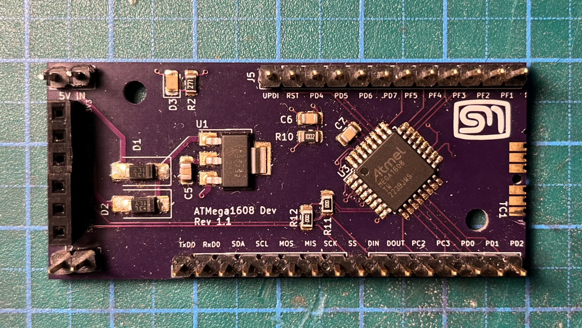
I created a custom development board to support the GPIO I was looking for. This has the additional benefit of being able to sort out any hardware design issues that could surface in the final product.
CONCEPT DESIGN
BLOCK DIAGRAM
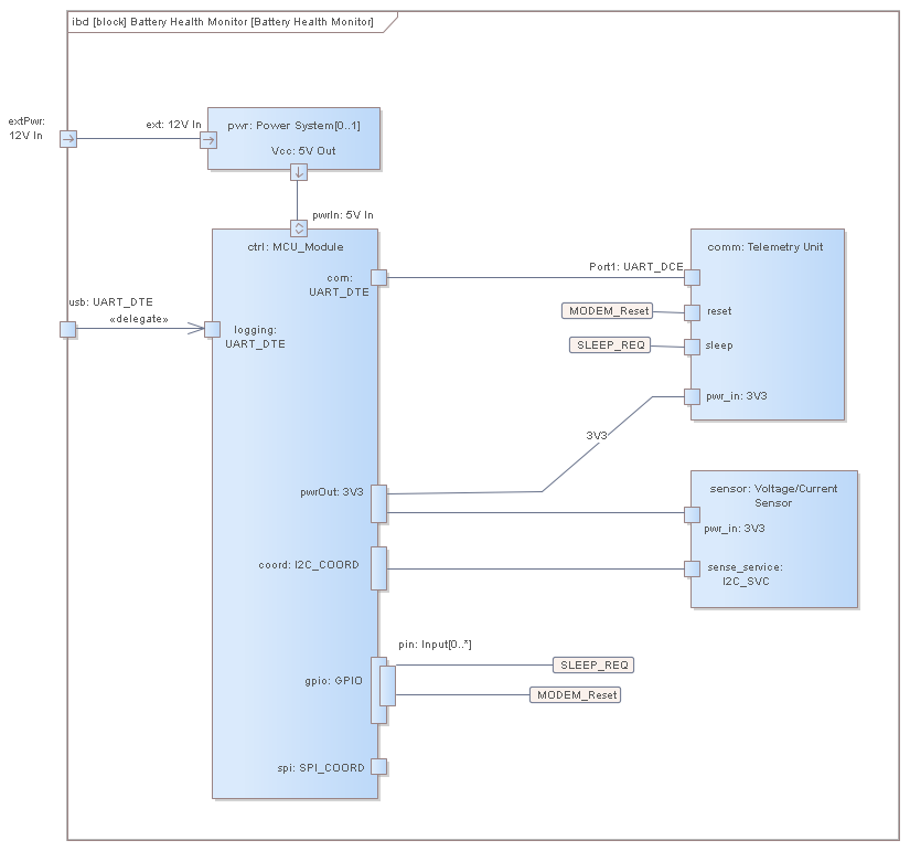
The block diagram depicts the physical aspects that were thought of some time ago. The original design contains much more but the extra aspects were removed for the scope of this project. The microcontroller module, i.e. the custom development board, interfaces with the Telemetry Unit i.e. the XBee module via a USART and the Voltage/Current sensor interfaces via I2C/TWI. There is then a spare UART leaving the block. I find these concepts important to maintain and not to be too specific about the implementation of the underlying modules. This helped to organise the code later.
STATE DIAGRAM
It was planned from the start to implement a Finite State Machine (FSM) as defined in the state diagram below. The device would power up and go through some initialisation steps and go into an idle state. After a determined amount of time, the device will wake, perform a reset (i.e. wake the MODEM) and send out a READY message on a broadcast address. This message should be received by a nearby gateway. The gateway will check if the node is known. If not, the gateway will send a NODE-INTRO-REQ message, whereupon the node will respond with a package of data introducing itself. If the node is known, then the gateway will respond with a DATA-REQ message. The node will then read the sensor information and package a DATA response for the gateway to record. When the node receive an acknowledgement that its messages have been received, it will put the MODEM and itself to sleep and be in the idle state. The broadcast address is only used when a gateway is not known. After the first interaction with a gateway, the node will save the address of the gateway for use next time.

MESSAGES
The messages sent between the sensor node and the gateway are based on a token/value structure. The goal was to be able to transmit data but still remain in the approximately 70 byte data frame limit for the XBee. The tokens are one byte values that are predefined to describe the data and metadata that the devices will deal with. The structure of the message always begins with the operation and then the serial ID of the transmitting device. The operation will dictate the rest of the structure. The serial ID for the current implementation is taken directly from the 10 byte device ID available in the ATmega. Ideally, this could also have come from some other external silicon serial ID device. But therefore the microcontroller serial ID comes for free.
#define HEADER_GROUP 0x10
#define OPERATION_GROUP 0x20
#define PROPERTY_GROUP 0x30
#define METADATA_DOMAIN_GROUP  0x40
#define METADATA_CLASS_GROUP  0x50


    typedef enum token_e {

        NODE_TOKEN_HEADER_OPERATION = HEADER_GROUP | 0x01,
        NODE_TOKEN_HEADER_SERIAL_ID = HEADER_GROUP | 0x02,
        NODE_TOKEN_HEADER_DOMAIN = HEADER_GROUP | 0x03,
        NODE_TOKEN_HEADER_CLASS = HEADER_GROUP | 0x04,

        // OPERATIONS
        NODE_TOKEN_READY = OPERATION_GROUP | 0x01,
        NODE_TOKEN_DATAREQ = OPERATION_GROUP | 0x02,
        NODE_TOKEN_DATA = OPERATION_GROUP | 0x03,
        NODE_TOKEN_DATAACK = OPERATION_GROUP | 0x04,
        NODE_TOKEN_NODEINTROREQ = OPERATION_GROUP | 0x05,
        NODE_TOKEN_NODEINTRO = OPERATION_GROUP | 0x06,
        NODE_TOKEN_NODEINTROACK = OPERATION_GROUP | 0x07,

        NODE_TOKEN_PROPERTY = PROPERTY_GROUP|0x00,
        NODE_TOKEN_PROPERTY_BUS_VOLTAGE = PROPERTY_GROUP | 0x01,
        NODE_TOKEN_PROPERTY_SHUNT_VOLTAGE = PROPERTY_GROUP | 0x02,
        NODE_TOKEN_PROPERTY_LOAD_CURRENT = PROPERTY_GROUP | 0x03,

        // METADATA
        NODE_METADATA_DOMAIN_POWER =  METADATA_DOMAIN_GROUP | 0x01,
        NODE_METADATA_DOMAIN_CAPACITY =  METADATA_DOMAIN_GROUP | 0x02,
        NODE_METADATA_DOMAIN_RATEY =  METADATA_DOMAIN_GROUP | 0x03,

        NODE_METADATA_CLASS_SENSOR =  METADATA_CLASS_GROUP | 0x03,
        NODE_METADATA_CLASS_ACTUATOR =  METADATA_CLASS_GROUP | 0x03,

    } Token_t;
READY
The READY message alerts the gateway that a node is attempting to communicate. The gateway will validate the source of the message and will then respond directly back to the node with either a NODE-INTRO-REQ, if the node is not known, or a DATA-REQ if the node is known to the system.
| Byte 0 | Byte 1 | Byte 2 | Byte 3 -Byte 13 |
|---|---|---|---|
| 0x11 (OPERATION) | 0x21 (READY) | 0x12 (SERIAL_ID) | Device Serial ID |
DATA
On receipt of a DATA-REQ, the node will collect the information that it is to send and package this into a data frame and send this to the gateway. The structure of Data message is shown below. From byte 14, this becomes a repeating group of a one bye property token and then a four bye property value.
| Byte 0 | Byte 1 | Byte 2 | Byte 3 -Byte 13 | Byte 14 | Byte 15 | … | … |
|---|---|---|---|---|---|---|---|
| 0x11 (OPERATION) | 0x23 (DATA) | 0x12 (SERIAL_ID) | Device Serial ID | Property 1 token | Property 1 value | … | … |
NODE-INTRO
On receipt of the NODE-INTRO-REQ, then node will respond with the information that describes the node. This will include the domain and class of the device and then a repeating group of one bye property delimiter and a one byte property token.
| Byte 0 | Byte 1 | Byte 2 | Byte 3 – Byte13 | Byte 14 | Byte 15 | Byte 16 | Byte 17 | Byte 18 | Byte 19 | … | … |
|---|---|---|---|---|---|---|---|---|---|---|---|
| 0x11 (OPERATION) | 0x23 (NODE-INTRO) | 0x12 (SERIAL_ID) | Device Serial ID | 0x13 (DOMAIN) | Domain token | 0x14 (CLASS) | Class Token | 0x30 (PROPERTY) | Property Token | … | … |
Domain and Class
The domain and class is a way to describe the type and purpose of a node.
- DOMAIN
- POWER
Devices of this time operate in the power domain. This means that they can measure or even provide controls. - CAPACITY
The capacity domain concerns the measurement of volume. - RATE
The rate domain is concerned with the capturing flow or movement information.
- POWER
- CLASS
- SENSOR
A sensor class device is expected to read some sensor value and provide this information in response to a DATA-REQ from the gateway. - ACTUATOR
An actuator class device enable some action to be performed in the field.
- SENSOR
IMPLEMENTATION
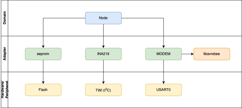
The first thing I needed to do was organise the code, or at least understand how it should be organised in such a way that I could test the individual aspects. The idea was to follow on from what I learned from Test-Driven Development with Python by Harry Percival and divide the code into modules and consider these modules in different conceptual areas such as Domain modules and Adapter modules. The Domain modules consider the business aspects of the logic and are agnostic to the underlying hardware being used. It is the adapter’s job to provide a simplified interface between the domain modules and the actual hardware peripherals. The idea here is to then create code that theoretically should be able to be ported to another device with only the adapters needing any changes. Equally, in the case of this node, if we change the type of modem being used, then as long as the adapter interface does not change, the node should still operate.
The problem came with my understanding of using Unity and CMock. I found the documentation very simplistic which created a challenge to apply these concepts with no previous experience. The Test Driven Development for Embedded C by J. W. Grenning was a great resource. Although I tried to maintain the Domain/Adapter concept, I did make some design/implementation decisions not to abstract too much since I was intending to work only in 16K of program space.
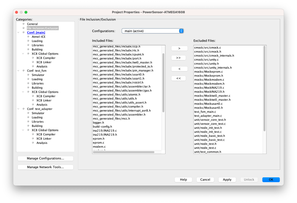
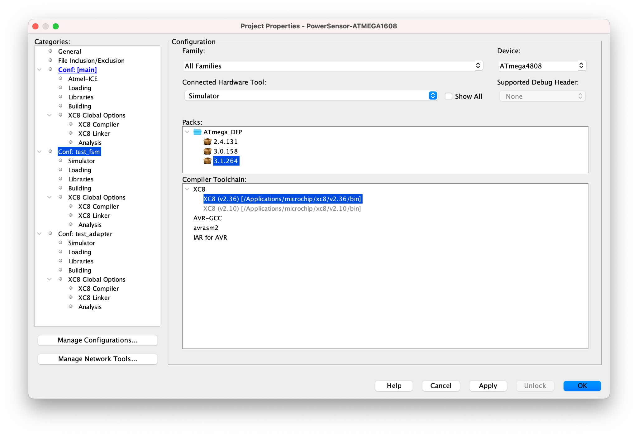
I had to find a way in which to be able to patch in the mock modules to be used by the tests but not break the build to be deployed to the target device. I found that the profiles as given in the MPLAB integrated development environment became very useful. I had previously never really taken much notice of profiles but now I see real value in the feature. I left the main profile configured for the ATmega1608 and with the main.c file as the main entry point. For the tests I created a profile for each of the domain and adaptor tests respectively. They each had their own main file to host the main(void) function and I included and excluded the C and head of files that each of those profiles required. When using CMock. It was important for the test profiles to be configured with the Simulator only and not any ISP tool. This would ensure that the tests would run locally and not need any hardware. I found this a significant improvement to the development workflow in itself. I could get immediate feedback on the success of the test without using any hardware. This meant I could work in my lab or on a laptop on the dining room table since I could run the tests anywhere, anytime.
LIBAVRXBEE
I had decided on using the libavrxbee utility from Nick Harris to help with the creation of the XBee messages. This library does not interact with the radio module. It will only help to prepare the data for transmission or for receiving.
I had issues with getting the library to work correctly, particularly with larger messages. I found an entry that mentioned that the x8-cc compiler does not support the malloc API on 8-bit machines as the memory is too restricted to use this API safely. The libavrxbee library uses this API in a couple of places. I made some small changes to the library to accommodate fixed sized arrays rather than allocating space. I figured I could justify this change since my usage of the library was very specific and the number and type of messages were finite.
The Test Driven Development approach was helpful in proving the changes. I created the expected XBee message frames using the XCTU utility from DIGI International. These messages could be compared to the data created by the libavrxbee library and were then included in the test cases as the expected values.
TEST CREATION
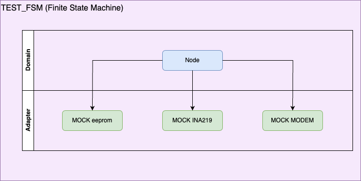
The CMock utility was an excellent tool but did take some getting used to. Particularly when devising tests for USART where a call to the underlying peripheral API accepts or returns one byte at a time. Here I took the tips from J. W. Grenning and structured the code so that it could be tested. As mentioned above, I had three profiles, main, test_fsm and test_adapter. For the Finite State Machine (test_fsm), I had a set of mock adapter modules. This way I could focus on the business aspect and this set up the expectation on what interfaces the adapters should support.
In the adapter set of tests (test_adapter), I focused only on testing the public functions and used mocks for the actual hardware peripheral modules.
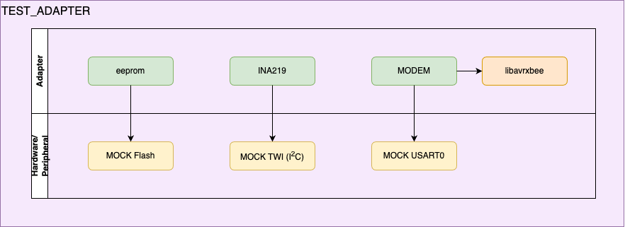
Adapter tests don’t need to be concerned with the main Node module. They only need to implement the public APIs and use the mock hardware peripheral modules.
The MPLAB tool set i.e. xc8-cc reportedly supports a stimuli file during debugging. This enables IO for the USART etc to be predefined for the purpose of testing. I struggled to get this working. This does not mean it does not work. My understanding of this limits me to have a clear idea of what steps I need to perform to get it working and my patients drew me to the features of CMock to set up what I refer to as fixtures. That is to programatically predefine the expected information to and from the I2C/TWI and USART.
The features of interest are
- Ignore
- Functions that are part of a mock and are potentially called multiple times but are of no interest to the specific test can be ignored.
- Callback
- This enabled content to be recorded to an array as a form of spy that could be inspected after the function under test completed.
These features of CMock were mentioned in various blogs, however, the samples did not quite work for me out of the box as had been implied. I found that I needed to create a configuration file for CMock that would provide these implementations.
:cmock:
        :plugins:
            - :ignore
            - :callback
            - :return_thru_ptr
ruby cmock/lib/cmock.rb -oproject.yml mcc_generated_files/include/twi0_master.hAs development progressed and the number of mocks and tests increased, I soon found that the program and data space of the ATmega1608 soon filled, blocking me from further development. Using the profiles meant that I could change the target device to the larger ATmega4808, which is a compatible AVR series-0 device. There I had enough Flash and data area that could comfortably accommodate further Unity tests and CMock modules.
FEATURES
LOGGING
An original design concept was to have printf configured to use USART1 as a channel for logging. I soon realised that the format strings used in printf would also soon have an impact on the program space. I could have shortened or removed the statements but I did not want to compromise the quality of the logging. Switching the test profiles to the ATmega4809 helped a great deal, but I felt there was more that could be done. This became apparent when I was at the stage of assembling the components to flash to the target device. The logging was causing the build to fail on the ATmega1608. I therefore introduced the concept of logging levels. Such concepts are not new. I introduced a set of macros for the various log levels controlled by an object macro called LOGGER_LEVEL. Behind the scenes, the preprocessor would only include in those logging statements that were defined for their respective level. All others would be excluded from the compile.
#define LOGGER_LEVEL_OFF 0
#define LOGGER_LEVEL_ERROR 1
#define LOGGER_LEVEL_INFO 2
#define LOGGER_LEVEL_DEBUG 4
#define LOGGER_LEVEL_ALL 7


#if defined(LOGGER_LEVEL) && LOGGER_LEVEL > LOGGER_LEVEL_OFF
    #define LOG_ERROR(args...) {printf("ERROR: "); printf(args); }
#else
    #define LOG_ERROR(args...)
#endif

#if defined(LOGGER_LEVEL) && LOGGER_LEVEL > LOGGER_LEVEL_ERROR
    #define LOG_INFO(args...) {printf("INFO: "); printf(args); }
#else
    #define LOG_INFO(args...)
#endif


#if defined(LOGGER_LEVEL) && LOGGER_LEVEL > LOGGER_LEVEL_INFO
    #define LOG_DEBUG(args...) {printf("DEBUG: "); printf(args); }
#else
    #define LOG_DEBUG(args...)
#endif
The table below shows the relationship to the specified logging level and the resource usage. On the ATmega1608, with DEBUG configured, the code fails to build for this target. I never felt that this was an issue since these debug statements were mainly of use for debugging with the tests.
| PROFILE | PROGRAM OFF | INFO | DEBUG | DATA OFF | INFO | DEBUG |
|---|---|---|---|---|---|---|
Main (ATmega1608) | 74% | 96% | FAIL | 51% | 51% | FAIL |
Test_fsm (ATmega4808) | 39% | 65% | 70% | 30% | 30% | 30% |
Test_adapter (ATmega4808) | 50% | 82% | 90% | 39% | 39% | 39% |
| Node Logging |
INFO: FSM_READY_STATE: Sending READY |
| Gateway Logging |
DEBUG:main:heartbeat |
| DEBUG Debug level from a test output |
INFO: =============== ready_data_collection_test ==================== |
SLEEP MODE
One of the important design goals was to put the system to sleep when in idle mode. This would be my first attempt at exploring this feature of the microcontroller. It would also mean having to put the XBee radio module to sleep as well.
To achieve this I employed the Period Interrupt Timer (PIT) which can be configured to trigger an interrupt every 30 seconds – RTC prescaler Oscillator set to 1kHz, the RTC prescaler Oscillator with a PIT period selection of 32768 cycles. My goal was to have the node sleep for up to 24 hours, so this was not going to suffice. I found a post that suggests calling the sleep_mode() API in a loop to create a longer sleep period. The loop would sleep for 30 seconds, way, check the iteration and go back to sleep. The average power usage over time for this quick wake-check-sleep is acceptable.
The next challenge was to put the XBee to sleep. There is a SLEEP_RQ pin. It was not enough to set this pin high to put the device to sleep. First the device needed to be configured using XCTU. The Sleep Mode (SM) option needed to be set to the appropriate sleep mode. In my case SM = 1 – Pin Sleep. Secondly pin D8 had to be configured to support the sleep signal D8 = SLEEP_REQUEST input. The table below shows the current draw during the various states of the node. A good portion of the 9 mA load during the idle time can be attributed to the power indicator LED that is installed on my development board.
| STATE | LOAD |
|---|---|
Idle | 9 mA |
READY | 43 mA |
NODE INTRO | 43 mA |
TOOLS
CONCLUSION
The sensor node was a complex project with many aspects. The envisaged device had to implement a finite state machine and adhere to a protocol as well as achieve other design goals. The Test Driven Development approach helped to break the system down to the various components and tackle them individually. I could first concentrate on the domain level aspects and leave the actual hardware implementation to later when I had more understanding of what it was I wanted from the interfaces to the hardware. The mock and testing frameworks were instrumental in creating uniform tests that did not have to consider the inner workings of their dependencies. I can’t say that I followed the Test Driven Design paradigm to the letter. My use of this technique is still work in progress. Overcoming the temptation to create code before the tests was hard and I certainly gave in a few times. I found it curious how my limited understanding of Unity and Cmock actually blocked me from establishing a list of tests as prescribed in the text. As my understanding on how to use these frameworks grew, then my ability to apply TDD also improved. I look forward to the next opportunity to apply the tools and techniques and to improve my skills in this area.
LESSONS LEARNED
There were many lessons learned on this project as there were many issues to resolve. Here is a rough list of the areas and what I was able to achieve.
- Build process
- the use of build profiles
- How to run the build from the command line
- Manages the object files to be compiled and linked
- Helps to manage the target device
- Unity
- Building complex tests
- Cmock
- Generating mock code
- configuring Cmock to generate specific APIs
- EPROM
- Reading and writing to the EEPROM
- Serial ID
- Reading the serial ID of the microcontroller
- Sleep
- Initiating and waking from sleep mode
- forcing the XBee module into sleep mode
- Macros
- Creating function type C macros
NEXT STEPS
The tests are passing and the node is communicating with the gateway and the data is reaching the database. However the node is a collection of development boards and jumper wires. The end-to-end testing is positive but I still need a deployable device. The next step will be to package the hardware so that I can deploy it in the field. Further tests can then be developed to see how the gateway reacts to multiple sensor nodes.
I feel that I have only scratched the surface of Unity and Cmock. I feel there are improvements to the way in which I have implemented the tests.
REFERENCES
- Grenning, James W., Test Driven Development for Embedded C, Dallas, Texas: The Pragmatic Bookshelf, 2011
- Percival, Harry J. W., Test-Driven Development with Python: Obey the Testing Goat: Using Django, Selenium, and JavaScript, Sebastopol, CA: O’Reilly Media, 2017
- Mark VanderVoord, Mike Karlesky, and Greg Williams, Unity: Throw the Switch, 2015
- Mark VanderVoord, Mike Karlesky, and Greg Williams, CMock: Throw the Switch, 2015
- Harris, Nick, Transmitting Data using an XBee and AVR using libavrxbee: Cheaply Made, 2015
- INA219 High Side DC Current Sensor Breakout – 26V ±3.2A Max: Adafruit, 2012
- Github Repository PowerSensor-Atmega1608
- Creating a Gateway Node using XBee and Test Driven Development

Nice Steve. This makes me want to get my XBees out, maybe in the new year.
Thanks
Mike
LikeLiked by 1 person
Thanks Mike, They are certainly fun to work with.
LikeLike