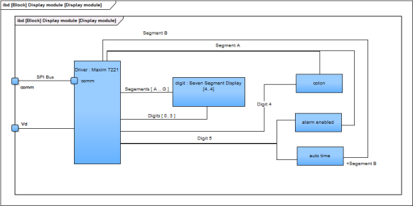
Well, not exactly back to the drawing board for everything… What has developed since doing the actual schematic is that the display module was treated as a black box. Now it is time to open this up and understand how this is to work. The beauty of this approach is that not knowing anything about the display module has not held me up on the other, simpler aspects of the project. This module is possibly going to be the most challenging. There are several dynamic elements to it and it is also going to be the module that will draw the most current. So far I have indicated that this module will be supplied by Vbb i.e. +5V and will be interfaced with the controller via a SPI bus.
The first challenge is which direction to take this. I find myself at a bit of a cross roads. Searching the internet for a suitable example as a starting point, I see there are already 7-segment display driver from Maxim i.e.  MAX7221. The advantage here is that it provides many features that make the implementation of a clock display relatively simple. I have quickly put together the block diagram that shows the intended implementation. It seems I could use the fourth and fifth digits to drive the colon and auto-time and alarm enabled indicators. The implications on the driving current need to be ratified.
The down side is the cost and the power consumption. It would mean rethinking my use of the MCP1703T-5002E/CB as the main regulator since this is limited to 250mA only. In reality, for practical purposes, even 250mA is to high for an appliance that is expected to be running 24×7 such as a digital alarm clock.
The alternative to using the display driver is to implement this myself. The advantage there is I am free to introduce what behaviour I need for the module to work within this project. The disadvantage is additional complexity in firmware updates. There will be two micro-controllers to contend with. At this stage, I have not done any calculations to see if there would be a saving in cost or power drawn by going the home-made route.
The block diagram for the micro controller based display module is very similar. The micro controller is used to replace the behaviour of the display driver chip. Although an ATMega88 is depicted here, any suitable i.e. low powered micro controller would suffice. As long as the duty cycle on the LED segments and indicator lamps is enough to provide a clear display.
Where to now?
Since I am at a cross road, the best way forward is to try things out. This is probably not good SysML practice since the design is not actually complete. But prototyping must be considered a part of design. I don’t have enough information to make a sensible decision as to the direction. The best way forward is to implement a prototype of the two possibilities and make the best choice from there. In this case I will be able to measure physical performance and power consumption and not relay on theoretical calculations.

