
A first project for the MaxiMite 2
I have been working on a new project idea. A device that could check the continuity and connections of a series of cables – namely the coaxial cables connecting LNBs on a satellite dish to the multi-switch. For this I need to drive several channels. In working through the design I wanted to explore two approaches. One approach uses encoders/decoders. The other approach uses shift registers. This gave me the opportunity to take advantage of a new addition to my bench – a MaxiMite 2 compact computer. In this post I will describe the two approaches and my first impressions of the MaxiMite 2 for the purpose of prototyping.
THE IDEA
On my satellite dish, I have two LNBs and a terrestrial antenna. Each LNB has four cables attached. This means, in total I have 9 cabels. I wanted to be able to test each of these cables with the one device. It should be able to determine continuity, short circuit and incorrect connections.
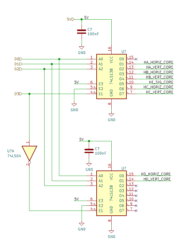
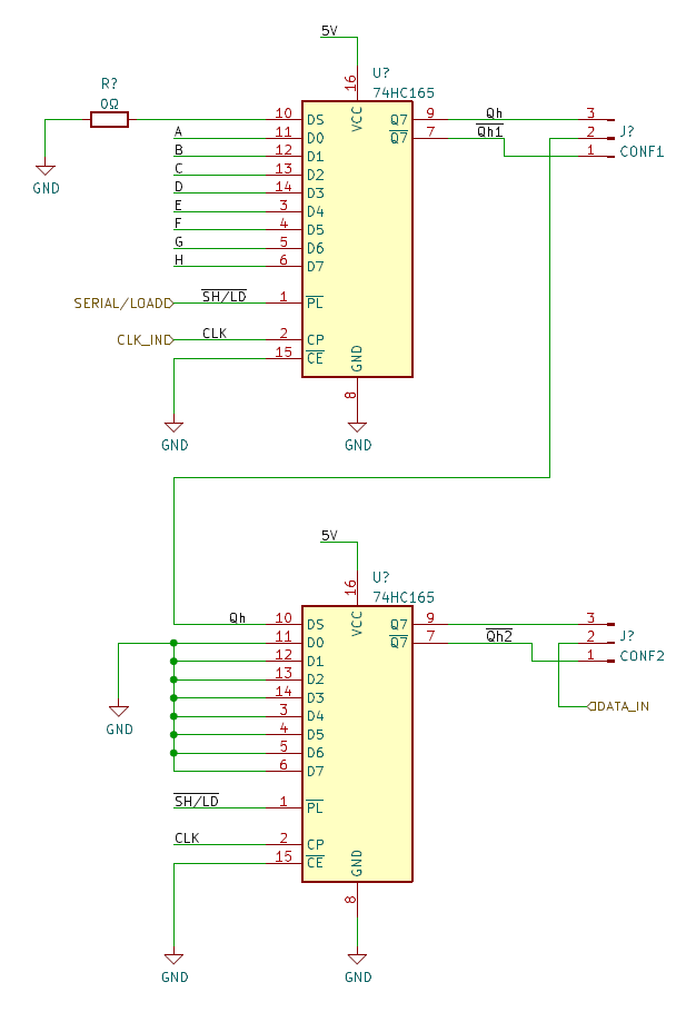
I decided to try out two ideas to achieve this. The first idea was to use a set of encoders/decoders – 74LC138 and a CD4532. These would be connected in such a way that the output of the 74LC138 would feed into the respective input on the CD4532. Using three lines, I could address up to 8 channels. In the second idea, I used a set of shift registers – 74HC5495 and 74HC165. Again, these would be connected so that the output of the 74HC5495 would feed into the respective input of the 74HC5165.
Since the simple configuration of these designs only supported 8 lines, I needed to cascade each configuration to achieve the 9 lines that I required.
DESIGN
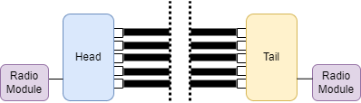
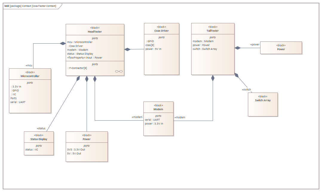
The focus of this post is not really the full device but rather how to implement one part. But a short overview of the goal helps to give context. The design is to have two separate devices. Each one connects to each end of the cables under test. The cables at the multi-switch are connected to specific ports. I also use similar nomenclature but this has no functional meaning. It is just a way to identify the separate channels. In order to conduct the test, there needs to be a way to open and close the connections between the coaxial cable core and shield. For this I envisage two separate devices. Just to give them a name, I refer to these as Head and Tail meaning that one is installed at the head of the cables and the other at the tail end. In order to coordinate the opening and closing, I imagine two small radio units. The Head device would then issue commands to the tail end to open or close specific channels or all channels.
The table below shows the nomenclature on the multi-switch and how they map out to the tester channels.
| System | Band | Direction | Tester Channel |
|---|---|---|---|
LNB 1 | Low band | Vertical | 1 |
Horizontal | 2 | ||
Hi Band | Vertical | 3 | |
Horizontal | 4 | ||
|
Terrestrial | 5 | ||
LNB 2 | Low band | Vertical | 6 |
Horizontal | 7 | ||
Hi band | Vertical | 8 | |
Horizontal | 9 |
| Test | Remote Instruction | Core | Shield | Interpretation |
|---|---|---|---|---|
Short circuit | OPEN ALL | N – High | N – High | Fail. Short circuit |
N – Low | OK. | |||
Continuity | CLOSE N | N – High | N – High | OK. |
N – Low | Fail. Open circuit | |||
False connection | CLOSE ALL | N -High | EQUATION: N – High | Fail. Wrong connection |
| ALL Low | Fail. Open circuit |
Encoder and Decoder
The technique using the encoders and decoders cascades the 74LS138 ICs in such a way that they can be driven with four lines to achieve 16 channels. Because of the way in which the decoder works, I did not want to use output Q0. This is active when the 4 input lines are low. I.e. it represents a 0 and so the Q0 line is low.

Shift Registers
I needed to program the shift registers. For this I employed a MaxiMite 2. I had only just received it and thought this was a reasonable first project.

PROGRAMMING
The first configuration requires no special programming at all. The hardware is configured to take binary decimal values and these will be instantly reflected on the output lines of the decoder. The same applies on the input side. The input lines to the encoder will be interpreted back into a binary decimal value. This means comparing the input values to the output values should determine the various states of open, continuous, short or false connection.
SUB shift_out value%, bitCount%

  ' print "Sending " value% " with " bitCount% " bits"

  pin(latch_pin) = 0
  pin(data_pin) = 0
  pin(clock_pin) = 0

  local pinState = 0, bit as integer

  for bit = (bitCount% - 1) to 0 step -1
    pin(clock_pin) = 0
    if value% and (1 << bit) then
        ' print "    " bit ": 1"
        pinState = 1
    else
        ' print "    " bit ": 0"
        pinState = 0
    end if

    pin(data_pin) = pinState
    pin(clock_pin) = 1
    pin(data_pin) = 0

  next bit
  pin(latch_pin) = 1
  pin(data_pin) = 0

END SUB


function shift_in ( bitCount% )
  ' print "Reading " bitCount% " bits"

  ' Load the registers in parallel
  pin(shift_load) = 0
  pin(shift_load) = 1

  local value%, bit as integer, pinState as integer

  value% = 0
  for bit = (bitCount% - 1) to 0 step -1
    pin(clock_in) = 0
    pinState = pin(data_in)
    ' print "    " bit ": " pinState
    value% = value% or (pinState << bit)
    pin(clock_in) = 1
  next bit

  shift_in = value%

end function

CONCLUSION
The encoder/decoder configuration was a nice standalone configuration. It required no microcontroller to test out the operation and get the results.
The shift register configuration required fewer parts than the encoder/decoder configuration but therefore required a microcontroller. The MaxiMite 2 was new on my desk and I was looking for an opportunity to get started with it. This proved an ideal choice. The task was specific and exposed me to many aspects of using MMBasic for interacting with other hardware.
