
I wanted to learn how to use a 128×64 pixel display, i.e. the DOGM-128-6 from Display Visions. I then got distracted by the requirements of the LED backlight. For several of the backlight options they suggest some series current limiting resistors for 3.3V and 5V. For the White, Blue and Full Colour backlights, they suggest using the CAT4238. I could not locate this device through my usual suppliers so I decided to see how far I could get with something that I thought was similar. I opted for the BCR421UW6. In this post I describe how I went about testing the device to get a better understanding of its use and if this would be a good fit for the intended purpose.
The BCR421UW6 is a more simpler device than the CAT4238 in that it only requires an optional resistor, whereas the CAT4238 requires an inductor and some capacitors. This is where my comparison of the two ends and I will be concentrating only on the test and usage of the BCR421UW6. I first became interested in a constant current regulator when reviewing the datasheet for the DOGM-126-6. I realised that I was lacking some fundamental understanding with these device. A particular difficulty I had was understanding how this device was to be used i.e. how does the current remain constant over a varying input voltage? I found the naming of the pins also confusing. A pin named OUT is connected to the cathode of the string of LEDs. The third item that was not clear was the selection of the external resistor REXT to achieve higher currents. The datasheet does not supply any empirical formula to calculate this. It only refers you to the graph of REXT Vs IOUT.
Goal
The main goal of this experiment is quite simple. To verify the usage and operation of the BCR421UW6 in comparison with the datasheet. More specifically
- To understand the operation against a range of loads and voltage supplies.
- To understand the impact of REXT and how to select its value.
- Based on the datasheet for the DOGM-126-6 Determine the optimum configuration.
Materials
- 1 x BCR421UW6.
- 1 x breakout boards for the BCR421UW6 devices.
- 1 x Lab power supply.
- 1 x Breadboard.
- Several Connector leads.
- Voltage and Current meters.
- Several LEDs.
Procedure
The tests used three configurations for connecting the device as shown in the three schematics.
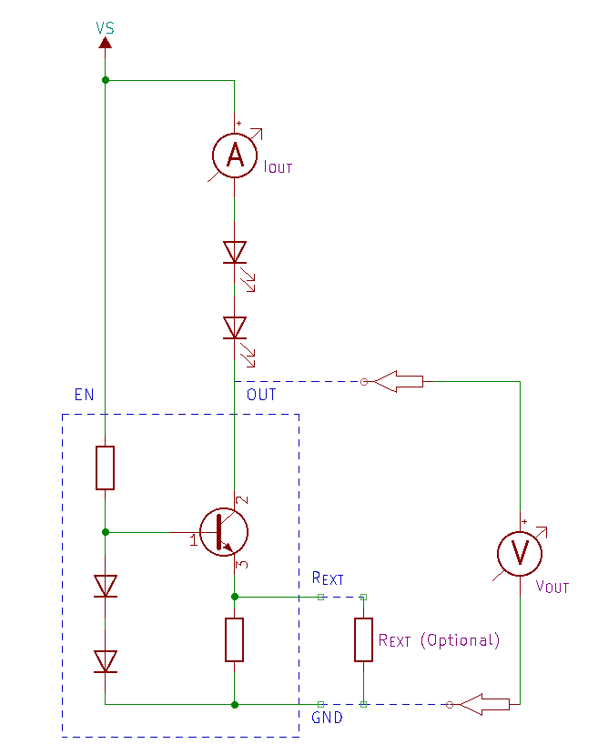
Test 1 – 2
- Connect the circuit as shown in Schematic 1, whereby VS and VEN are connected.
- Apply 3.3 V and 5V to VEN.
- Arrange the load of the LED string from 1 to 5 LEDs.
- Measure VOUT and IOUT for each LED added.
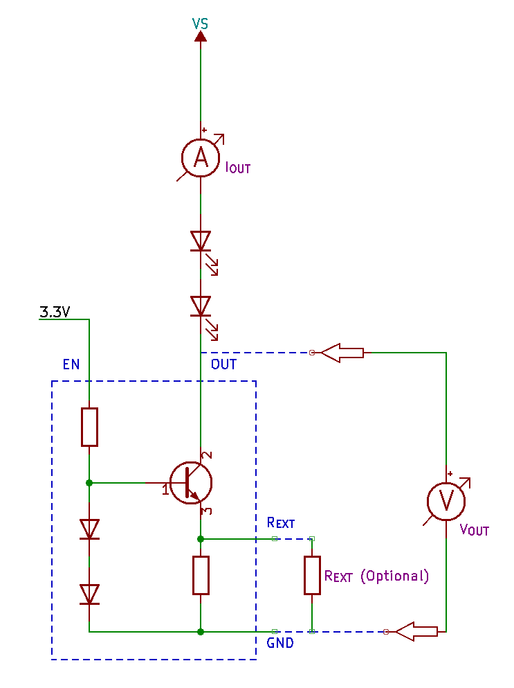
Test 3 – 4
- Connect the circuit as shown in Schematic 2 whereby VS and VEN are not connected together.
- Apply 3.3V to VS and 5V to VEN.
- Arrange the load of the LED string from 1 to 5 LEDs.
- Measure VOUT and IOUT for each LED added.
Test 5
In the fifth test, the circuit is connected as shown in schematic 2 but each time an LED is added, the VS is adjusted such that VOUT is 1.4V i.e. the minimum VOUT as described in the datasheet.
- Connect the circuit as shown in schematic 2.
- Arrange the load of the LED string from 1 to 5 LEDs.
- For each LED test, adjust VS such that VOUT is 1.4V
- Measure VS and IOUT for each LED added.
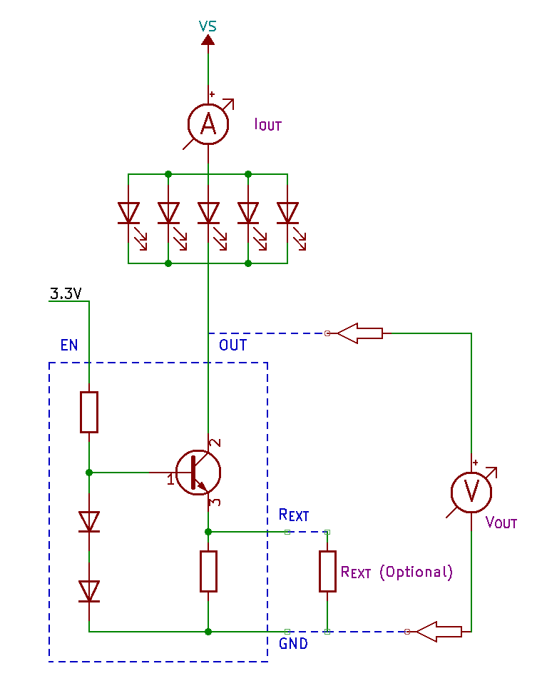
Test 6
For testing the use of the external resistor, schematic 3 was used whereby five LEDs were connected to VOUT in parallel.
- Connect the circuit as shown in Schematic 2, whereby VS and VEN are not connected together.
- Apply 3.3V to VS and 5V to VEN.
- Apply a range of resistors to REXT.
- Measure VS, VRXT and IOUT for each resistor added.
Results
Configuration 1.
VS = VEN = 3.3 V
LED VF = 1.9 V
| LEDs | VOUT (V) | Current (mA) |
|---|---|---|
| 1 | 1.37 | 11 |
| 2* | 0.14 | 3 |
| 3 | ||
| 4 | ||
| 5 |
* The device failed to operate
Configuration 2.
VS = VEN = 5 V
LED VF = 1.9 V
| LEDs | VOUT (v) | Current (mA) |
|---|---|---|
| 1 | 3.100 | 12 |
| 2 | 1.170 | 12 |
| 3* | 0.243 | 3 |
| 4 | ||
| 5 |
* The device failed to operate
Configuration 3.
VS = 3.3 V
VEN = 3.3 V
LED VF = 1.9 V
| LEDs | VOUT (V) | Current (mA) |
|---|---|---|
| 1 | 1.370 | 10 |
| 2* | 0.148 | 0 |
| 3 | ||
| 4 | ||
| 5 |
* The device failed to operate
Configuration 4.
VS = 5 V
VEN = 3.3 V
LED VF =1.9 V
| LEDs | VOUT (V) | Current (mA) |
|---|---|---|
| 1 | 3.06 | 10 |
| 2 | 1.18 | 10 |
| 3* | 0.16 | 0 |
| 4 | ||
| 5 |
* The device failed to operate
Configuration 5.
VEN = 3.3 V
VOUT = 1.4 (minimum)
LED VF = 1.9 V
| LEDs | VS (V) | Current (mA) |
|---|---|---|
| 1 | 3.31 | 10 |
| 2 | 5.19 | 10 |
| 3 | 7.08 | 10 |
| 4 | 8.96 | 10 |
| 5 | 10.88 | 10 |
Configuration 6.
VEN = 3.3 V
VOUT = 1.4 V
LED VF = 1.7 V (5 LEDs in parallel)
| REXT | VS (V) | VREXT | Current (mA) |
|---|---|---|---|
| 10Ω | 3.44 | 1.01 | 86 |
| 20Ω | 3.32 | 0.97 | 50 |
| 30Ω | 3.27 | 0.93 | 37 |
| 40Ω | 3.26 | 0.91 | 30 |
| 57Ω | 3.30 | 1.13 | 24 |
| 67Ω | 3.25 | 0.90 | 22 |
| 77Ω | 3.23 | 0.91 | 20 |
Discussion
When executing the first four tests, it became apparent that before the device will work effectively as described, VOUT must be at least 1.4V. It was found that once the accumulated forward voltage (Vf) of the LEDS exceeds VS – 1.4, then the device fails to operate. This behaviour inspired me to add test 5 to the list. This is where I could see the device operated effectively as described in the datasheet.
Test 6 differed from the previous five tests since I was applying different external resistors along with keeping VOUT at 1.4V. Graphing this information shows a result that is consistent with the datasheet for the REXT Vs IOUT graph.

Conclusion
The datasheet for the BCR421UW6 has all the information, however, I did not get a clear picture on how it should be designed into a use case. The datasheet makes no reference or assumption as to Vf or the current requirements of the LEDs. Without a concrete case, I was missing the point. The tests enabled me to provide that concrete use case and understand what I was missing and how to use the device. I believe the following steps could be used to help determine a ballpark supply voltage.
- Determine the current requirements for the LEDs. This would be based on the type of LED, the number of LEDs in the system and their configuration i.e. parallel or serial.
- Determine the input voltage, where by the VS should be determined using the following calculation

Where
| VS | Supply voltage |
| n | Number of LEDs |
| Vf | LED forward voltage |
- When the current requirement is greater than 10mA, then an external resistor REXT is required. The datasheet indicates that this can be determined from the REXT vs IOUT graph.
The original intent was a replacement part for the CAT4238 to use this to drive a backlight for the DOGM128-6. My tests actually show that the BCR421UW6 falls short of the mark for this usage. The DOGM128-6 datasheet says that the backlight has a Vf of 3.3V and that the current should not exceed 25mA. This is when they recommend to use the CAT4238 when having a supply voltage of 3.3V. My results show that I need at least Vf+1.4V=VS i.e. 4.7V for the BCR421UW6 to operate in this system. I grabbed the BCR421UW6 with the thought that any constant current driver should do. It turns out that this particular part requires a minimum of VS=5V. In this case the DOGM128-6 datasheet says if a 5V supply is used, then a 82Ω series current limiting resistor can be used.
References
- DOGM-128-6 128×64 – 2.3″ Display module
- CAT4238 Step Up Boost LED Driver
- BCR421UW6 Linear Constant Current LED Driver
- BCR42xUW6 Breakout board
