
Remote sensors are only one component of a much larger system. If the information they collect is to land on the internet somewhere, then there needs to be some type of bridge or gateway. In this post I take a look at using Test Driven Development (TDD) to create a simple gateway node. It is possible to subscribe to existing services using already established protocols. However, using this project as an example, I am able to explore applying TDD when interfacing with external hardware modules.
I have interfaced Python with external hardware modules before when I put together a small web application, using Django, to help control a stairwell lighting project. I have been interested in Test Driven Development for a while and have applied it to several non-python projects. I became more enthusiastic about the approach when I came across Test Driven Design in Python – Obey the Testing Goat. Working through this book, I was able to see how TDD could be applied literally from an empty directory through to deploying the application to an integration server and the target platform server. I was then keen to apply Test Driven Development again on my next embedded project. In working through the approach, I soon hit some challenges trying to apply the principles of this development approach when interfacing with external hardware. Many of the TDD examples describe only interacting with other software components and not hardware.
The Project
In order to get the data collected from a sensor onto some web application, we need a means to connect the sensor to the internet. Installing a WiFi modem into a remote sensor is possible but it would need to draw its power from something other than a battery. Therefore to go from the sensing device to the internet, we need an intermediate device. A gateway or bridge sits between two networks and is intended to provide the means to transfer information between the two networks. I decided to start with the gateway so I have something to build and test the sensors against and be able to see their data directly on the web application.
Design
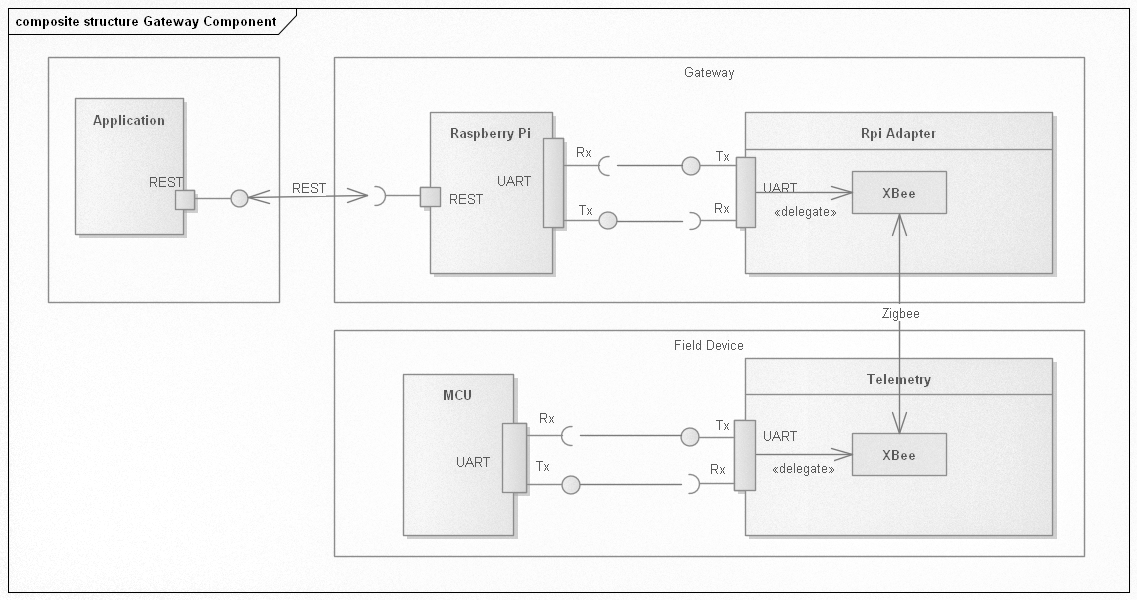
The component diagram shows how I envisaged the architecture of the communication from the sensor unit or field device through to the application hosted as a web application. The field device is equipped with a MCU, some type of sensing unit and an XBee modem. The gateway consists of a Raspberry Pi Zero and XBee to Raspberry Pi adapter – which I designed with KiCad. The communication between the gateway and the web application is direct using REST. I could have used MQTT and in an initial trial, I did actually do that. But I found, for my purpose, the additional work of starting up an MQTT server and all the administrative steps to secure the connection etc. it was better saved and just making a simple direct REST connection to the application. MQTT will still be considered in the future if this project grows (i.e. more gateways) to warrant the extra effort.
Protocol
With the communication medium worked out, there needs to be a formal specification of how the end devices will communicate with the gateway. Keeping things simple for this model, I decided that the communication should be initiated by the end device only. The reason for this is so that power is not wasted on constantly keeping the channel open on the end device in the event that the gateway will request information.

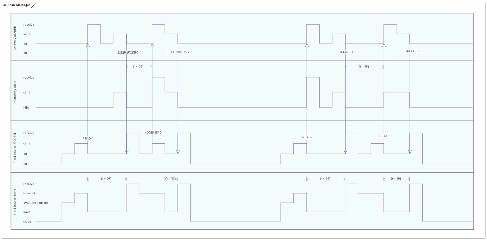
The activity diagram helps to describe the dialog.
- The dialog starts with the end device indicating that it is ready for communication. The end device will stay in this state for no more than 30 seconds. If there is no response from the gateway (i.e. it is busy with other devices) then the end device will go back into the idle state and try again later.
- When the gateway receives the READY event, the identity of the end devices is checked. If this is new to the gateway and the application, then the gateway will issue a request that the end device should introduce itself. The gateway does not wait in any state but will record that the request has been made. If the request has not been actioned within 30 seconds, then the record will be removed and the end device will still be unknown to the gateway.
- When the end device receives a message to introduce itself, then it will create a packet of information identifying what type of sensor it is and its serial ID. When this information is sent, the end device will wait another 30 seconds for the acknowledgement that the information has been received.
- In the case where the end device issues a ready event and is known to the gateway, then the gateway will issue a data request message. The end device can then package up the data that it has collected and send this to the gateway. The end device will wait for a data acknowledgement on successful receipt. If this does not arrive within 30 seconds, then the device will go back into an idle state and wait to be sent again later.
Even though the protocol is simple, there are still many corner cases of success and failure that I have not yet factored in. To be honest, I was waiting to see how this works and factor in the changes as the cases arrive rather than trying to think them out first.
Schematic

The adapter has a 2×6 2.54mm pin connector to connect directly to the Raspberry Pi. The board layout was such that the socket connector of this size does not interfere with the other pins on the connector. The XBee is powered directly from the Raspberry Pi Zero. As an experiment, I also added a SGM811 power monitor.
The power for the circuit comes directly from the Raspberry Pi. The power monitor was added to enable a clean start up of the XBee and also to interface the GPIO18 to be able to software control a reset.
Two indicator LEDs were added to help out with troubleshooting. I added a normally-closed solder bridge that can be cut any time to reduce the load.
The layout was simple enough. I opted to set most of the extra parts underneath the XBee module since there was space and just exposed the indicator LEDs and a pin header to connect a reset switch if one is needed.

Extra 3d models are from GrabCad.
Programming
Since I was using Raspberry PI and XBee radio modules, the hardware is largely given. The only piece that I needed to create was the adapter between the Raspberry Pi and the XBee module. Rather than launching into creating the custom board, I used a breadboard to see if there was anything else I needed to consider when designing the board. Therefore the major amount of work was actually in the coding. From previous experience I wanted to take a more controlled approach where I could quickly and easily run through the tests to be sure any changes would not result in regressions. The biggest challenge though was deployment. On previous projects, the development would start on a Windows machine but when trying to move to the target platform like Raspberry Pi, I found the setup and porting steps became tedious to the point where eventually all development moved to the target platform. I wanted to avoid this situation so it was important to keep a couple of design goals in mind.
- Be able to run unit and integration tests on any platform.
- Be able to deploy the gateway software with a minimal number of steps.
The book Test Driven Development with Python was an invaluable resource that I used as a guide – not only for creation of unit and functional tests in Python, but for setting up a deployment script so that I can keep developing and testing on the Windows machine and effortlessly deploy to the Raspberry Pi for final integration testing with one step.
Iterations
As planned, the development was done in iterations. The first iterations were actually attempts based on given examples for MQTT. This is where I decided that I was not ready to bring in all that infrastructure when I wanted a simple example up and running. I had to abandon that attempt and start again. This time I started with a basic structure thinking about what it was I was creating and its domain objects and what services this would require. In the initial iterations, I focused on just that and created modules within a directory structure that reflected the thinking of domains and services. As I was progressing, I built up the tests, adding modules along the way to make the tests pass. I enjoyed the fact that I could see progress unfolding as each set of tests were created to fail and would then eventually pass.

I initially found it difficult to build the tests for the radio units. I was considering all sorts of ideas on how to mock out the serial driver. But this was going to be a can of worms since the serial driver is very different for each platform. The blog article Cosmic Python – Testing External API Calls was brought to my attention along with the associated book Architecture Patterns with Python. Reviewing these made me realise that I just needed a slight change in perspective. While the radio modules use the serial connection, it was out of my application domain to be thinking I should mock those. The tip used in the book “Don’t mock what you don’t own” rang true. I therefore restructured the gateway application to use what I term as adapters. An adapter is a class in my module structure that handles the interaction with some external component or module i.e. the radio module library. Then for my unit tests, I created fake adapters and therefore these external resources were never touched. For the functional and integration tests the real adapters were used and the slower tests would operate on the real hardware. Therefore the main functional interaction is between the domain and services. The adapters are associated during the bootstrap of the application. The advantage of this approach, is that should I want to move to MQTT for the message bus or use LoRa for the modem then I should only need to configure a new adapter and associate that in the bootstrap. The functional interaction between the domain and services should stay the same.
A key component to the operation of the gateway, though it is not functional, is the config module. This supports the use of .ini type files to set the most common configuration parameters such as the port the modem is on. This class was created so that it would also handle the command line arguments such that any command line argument could be set within the configuration file and vice versa.
[general]
logfile = leawood_gateway.log
sleeptime = 5

[rest]
username = API_USER
password = PASSWORD-NOT-SET
rest = https://host/ords/leawood_dev/api/1.0

[modem]
serial-baud = 9600
serial-port = COM6
Bringing Gateway up Using the Custom Adaptor
I mentioned previously when constructing the software for the gateway, I did not have the custom adapter board for connecting the Raspberry Pi and XBee. The whole setup was done on a breadboard first to understand what I was working with. Once I got the software working, I could then send the board design off for fabrication, confident that I had something concrete to start with. When the board arrived I could assemble it and knew what I needed to check before plugging it all in and using it.
To avoid damaging the Raspberry Pi and XBee, I first applied power to the bare board. If there were any shorts, it would be a waste as I don’t have that many XBee modules and Raspberry Pis laying around.
Once satisfied that there were no shorts, I then plugged everything in and powered on the Raspberry Pi. The associated LED started blinking, which was a good sign.
Since the software was already deployed to the Raspberry PI, All I needed to do was start it up.
Getting the gateway running is reduced to a couple of steps – setting up the environment, deploying the application and then running the startup script.
. .venv\Scripts\activate

cd deploy_tools
fab deploy:host=<HOST CONNECTION>


python -m leawood -h
usage: __main__.py [-h] [-c config_file] [-v] [-u user_name] [-w password]
                   [-l logfile] [-r rest] [-s serial-port] [-b baud]
                   [-S sleeptime]
                   {start,stop} ...

Start and stop the gateway

positional arguments:
  {start,stop}

optional arguments:
  -h, --help            show this help message and exit
  -c config_file, --config config_file
                        The configuration file containing the common arguments
  -v, --verbose         Enable debug mode
  -u user_name, --username user_name
                        The username for the REST service
  -w password, --password password
                        The password for the REST service
  -l logfile, --logfile logfile
                        The name of the log file
  -r rest, --rest rest  The base ReST endpoint
  -s serial-port, --serial-port serial-port
                        The serial port for the XBee module
  -b baud, --baud baud  The baud rate for the XBee module
  -S sleeptime, --sleeptime sleeptime
                        The sleep time when waiting to request new information
Conclusion
I am happy with the result of this approach. Each time I go back to it, I only need to run the tests to remind me where I am up to and what needs to be done next. This is not to say that it is perfect. There are plenty of open items but at least I have a good framework in which to keep moving forward and improving the gateway. The key points I learned which are repeated in the references that I used
- Don’t mock what you don’t own.
- Refactor only on green.
Mocking or faking what is in the application domain, I have already touched on and this really helped move things forward. The other point is equally important and helps to keep the changes in manageable steps, knowing that at each step things were working. This also led me to realise it is OK to put something in place only to tear it up again later. One example, the original implementation of the configuration file was actually JSON.
Improvements
Some improvements and outstanding features
- Timeouts when waiting on the field devices to respond.
- This could also include a black list of suspect devices.
- XBee DigiMesh.
- I have been using Zigbee. I would be curious to try DigiMesh.
- Scan for the XBee unit across the serial ports.
- This has to be configured manually and can not really be relied on long term. A mechanism to find the modem on the serial bus would be useful. This is more of a problem on Windows for testing where the assigned port can change.
- Queue the send operations.
- The messages coming into the gateway are queued. Currently the sent messages are not.
Next Steps
While some of the listed improvements are important, I want to get moving on a sensor device. This will put the gateway through its paces, especially when I will have more than one sensor trying to send data. The main focus of this post was about the gateway and approach taken to create the software. I did not go into any detail of the web application. The design of which is also impacted on the design of the gateway. I intend to have another write-up about that later on when I have a more presentable model.
Reference
- GitHub Repository – doc.
- 3d Models used in KiCad – GRABCAD.
- Percival, Harry. Test-Driven Development with Python: Obey the Testing Goat: Using Django, Selenium, and JavaScript. Sepastopol, O’Reilly Media Inc., August 2017: 2nd Edition
- Percival, Harry & Gregory, Bob. Architecture Patterns with Python. Sepastopol, O’Reilly Media Inc., March 2020: First Edition
- Cosmic Python – Testing External API Calls

2 thoughts on “Creating a Gateway Node using XBee and Test Driven Development”