
Using simple lab gear to understand the theory
I was looking at ways to create a device to test some cables. When talking about my idea with others, the notion of Time Domain Reflectometry (TDR) came up. At first this looked to be out of my league, but I was curious all the same. In this post, I look at trying to understand the theory with my modest lab gear.
The goal is to understand the elements of Time Domain Reflectometry through examining the behaviour of a pulse on several lengths of coaxial cable.
MATERIALS
- Oscilloscope, Rigol DS1054.
- Function Generator, ELV DDS 8100
- A length of coaxial cable
- Connectors and adapters to connect the cables.
PROCEDURE
- Measure the cables for reference.
- Setup the function generator for 50% duty cycle and 100Hz
- Set up the Oscilloscope
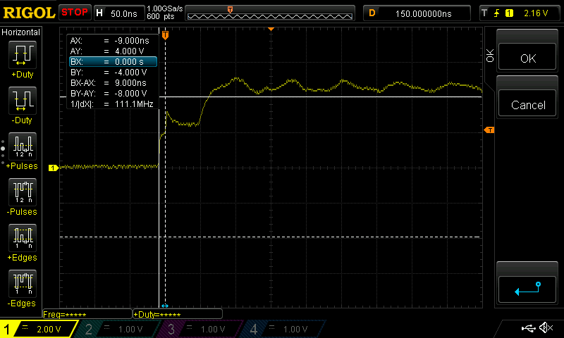
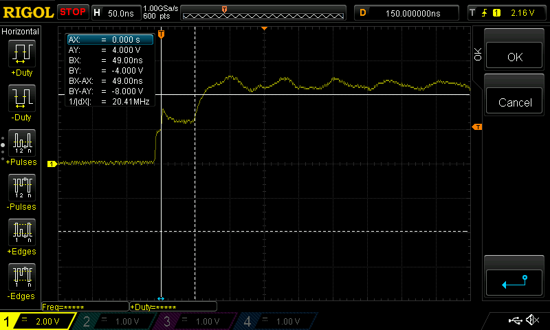
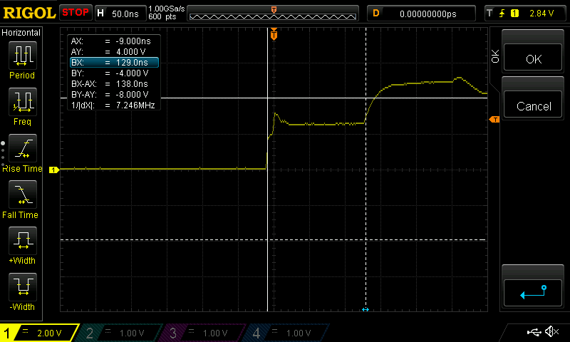
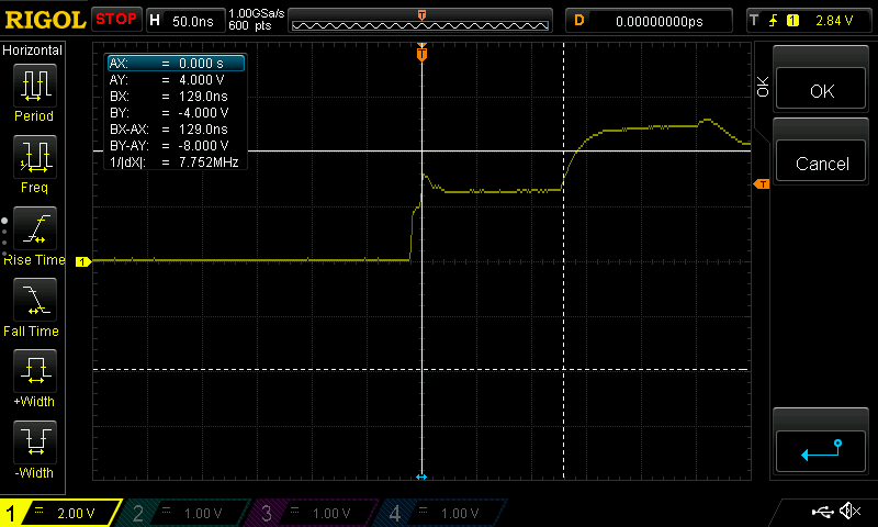
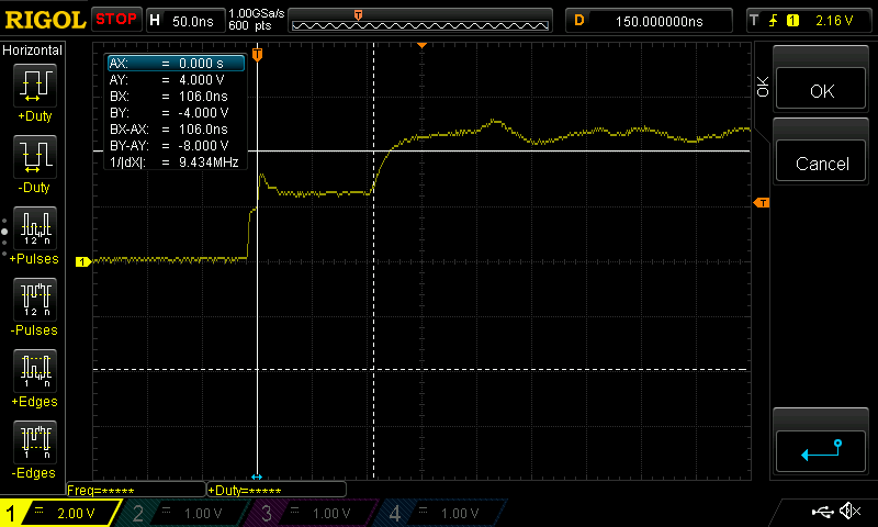
- Measure the time between the rises. Fig 1. Depicts the typical trace for a cable connected in this system. A measurement was made between points α-β, α-ψ and β-ψ. It is assumed that the first rise is the adapter cable and the second is the cable under test..

RESULTS
Cable Lengths
Cable Sample | Measured Length | Velocity Factor | Note / Cable Markings |
Cable A | 4.440 m | No markings | |
Cable B | 15.890 m | α x ing SKB 489 | |
Cable C | 9.780 m | Hama antennenkabel doppelt abgeschirmt | |
Connection Cable | 1.125 m |
Connection pulse measurement
Cable Sample | Distance α-β | Distance α-ψ | Distance β-ψ |
Cable A | 9 ns | 58 ns | 49 ns |
Cable B | 9 ns | 138 ns | 129 ns |
Cable C | 9 ns | 115 ns | 106 ns |
Cut Cable B | 9 ns | 97 ns | 88 ns |
Cable A

Cable B

Cable C


DISCUSSION
Based on some research of this topic, the measurements of the echoed pulse was performed by simply touching a voltage source onto the cable under test. It was based on this approach that I chose the lower frequency of 100Hz for the test.
It was found that attempting to calculate the theoretical length of the cables was not entirely possible since significant information is not available. The cables were simply what I had on hand. There was no additional information to describe the cable construction which would affect the cables characteristics. Instead, I looked at the problem in another way and attempted to calculate the Velocity Factor from the information available.

| Variable | Description | Unit |
|---|---|---|
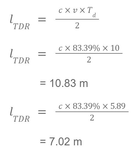
Ltdr | Length based on TDR calculations | m |
c | Speed of light | 2.9979 x10⁸ m/s |
v | Velocity Factor of the transmission line | |
Td | The round trip of the onset pulse and the reflection. | μs |
Velocity Factory Results
| Cable | Length (m) | Round trip (ns) | Velocity Factor |
|---|---|---|---|
Cable A | 4.44 | 49 | 60.45% |
Cable B | 15.89 | 129 | 82.18% |
Cable C | 9.78 | 106 | 61.55% |
Connection Cable | 1.125 | 9 | 83.39% |
After cutting cable B, I applied the calculated Velocity Factor to verify the length.
CONCLUSION
It was thought that I would be able to attempt to calculate the lengths of the cables under test. However, it soon became apparent that some significant information is missing, namely the Velocity Factor. The cables under test did not have any significant markings that would enable me to locate the appropriate information to either lookup or calculate the effective Velocity Factor.
I attempted to calculate the Velocity Factor using the same formula for calculating the TDR and then apply that to a cut cable. Here is where some discrepancies crept in. I could accept the calculation for the larger length as this was close to the measured length. However, the shorter length was too far out. I believe that while I could see the effect of TDR, to be able to calculate this correctly I would need a clearer idea as to where to place the cursor on the wave trace and to even experiment with different frequencies. I had actually used 100Hz. From other documentation I have seen, higher frequencies are used.
