
At the local open workshop ZAM, there came a project idea for a text display that is publicly available. After some experimentation with a commercially available unit – that proved to be too cumbersome for public use, we explored creating our own. In this post I describe how I adapted my original NeoPixel driver project – Expanding the NeoPixel Project – to create a text display unit still using an ATTiny 1614 and a single shift register.
The original concept for the project was described in a brief as part of a suite of projects. The basic concept was to provide a platform to where a message could be posted that is public.
EVERYONE has the same opportunity to write about themselves and EVERYONE can read it.
The transfer of what is digitally taken for granted into analogue everyday life creates a bridge between two realities that are increasingly taking for granted that they exist in parallel and whose interface is in the trouser pockets of passers-by. The text corner wants to break up this pattern.
At first a commercial unit was used. But the usage turned out to be cumbersome for the goal of the overall project. Then came the question to create our own. While researching what is involved in creating a text display, I was reminded of my design for driving some NeoPixel strips using an Atmel 1614 and a shift register.
Design
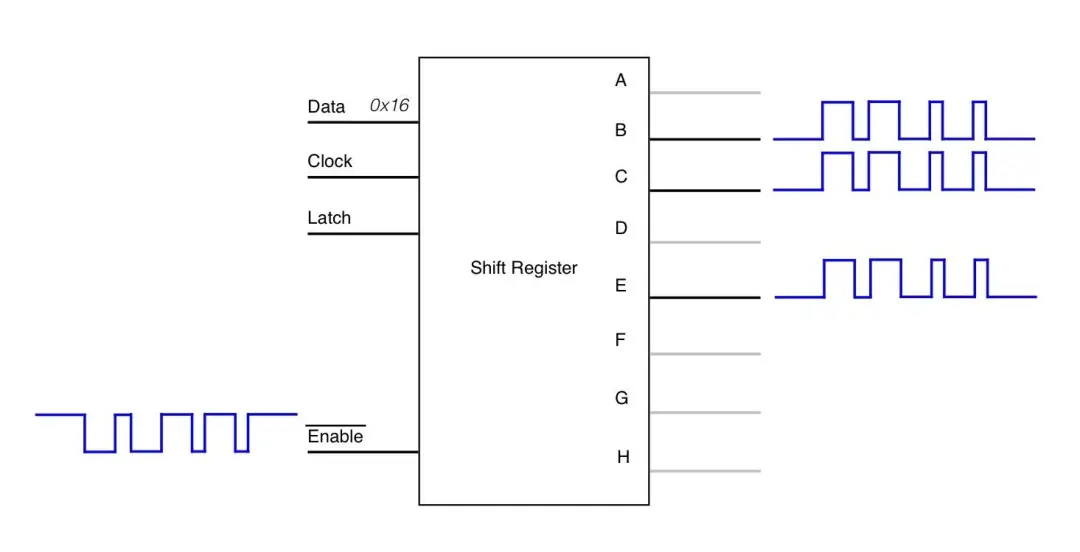
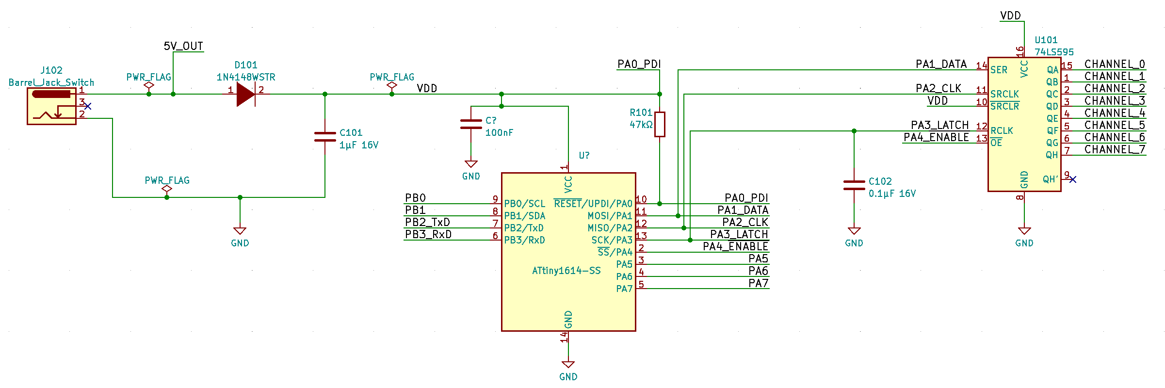
The design is exactly as it was for the original project i.e. using a microcontroller to drive a shift register where each output line of the shift register is connected to the data-in line of the NeoPixel strip. This has the advantage of driving more than one line at once. However in the case of the text display, that is not required but does give a simple way to multiplex the NeoPixel strips without taking up the GPIO lines from the microcontroller.
The diagram below, taken from the original project depicts the operation. Instead of a direct GPIO line driving each NeoPixel strip, they are driven via the output lines of the shift register. Rather than the microcontroller driving the data line, the enable is toggled with the timings to communicate the respective 1 Code and 0 Codes to the NeoPixels.
Unfortunately, I could not use the boards created for the original project as they only supported five NeoPixel strips. This original design decision was made since, at the time, I only needed five lines. The idea of allowing for them on the board but not populating the parts did not come to mind as I wanted to keep the board size as small as possible.
Aside from that obvious design constraint, there were several other problems to address in this new design.
- The creation and storage of the font.
- Minimising memory usage.
- Communicating new messages to the device.
Font Creation
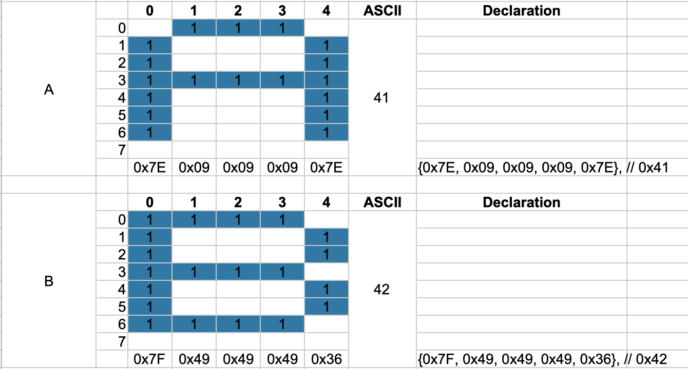
The creation of the storage font was achieved by treating each NeoPixel line as a row. Therefore I could model an 8×5 character matrix. I used a spreadsheet to help with the calculation of the data where a character is modelled as 1×5 bytes. i.e. each byte represented a column in the character matrix. I had to create such a structure for each character from ASCII 0x20 to 0xFF. Though I did not create characters for all but I did need to support the most common German characters such as ä, Ä, ö, Ö, ü, Ü, ß, and §.
Minimising Memory Usage
The Font Data
The ATTiny 1614 has 16K of FLASH and only 2K of RAM. This posed a problem with respect to the storage of the font data and then the RAM needed as display RAM. The font data was taking up 224 x 5 = 1,120 KB. Then there was the memory needed to drive the strips. In the original design I was using 5 x 60 x 3 = 900 Bytes. Since there was nothing else needed, I could afford this memory usage. But this time I could not.
The first thing I did was move the font information into the FLASH since this information will never change. Research showed that setting a static array as const can not be assumed that this will be stored in the FLASH. The compiler needs to be told about it by using the PROGMEM macro from avr/pgmspace.h
include <avr/pgmspace.h> |
Then we need to use the pgm_read_byte API to be able to read the values from the FLASH. To simplify the usage, I copied the character information from FLASH into a local array on one block
uint8_t font_char[5]; |
Revisiting the Colour Encoding
In the original NeoPixel driver, I simply used three bytes for each pixel. One each for Red, Green and Blue. This simplified the the operation of sending the data to the pixel strip since I only needed to traverse the array and literally bit-bash the shift register. However for the text display I could make the design decision that a character will only be one colour. By limiting the range of colours to a pallet of colours, I could reduce the display memory to one byte per pixel i.e. each byte of the strip array would contain a reference to a predefined colour. I created a colour chart to hold only the seven colours of the rainbow plus one for white and one for black (all LEDs off). Taking what I had learned from the storage of the font, there was no reason to keep this table in the heap but push this into the FLASH with the PROGMEM macro.
Using a colour code like this instead of the actual pixel colour information, I was able to reduce the heap usage for colour data from 1.440 KB to 480 Bytes. The compiler stats show that I reduced memory usage from 95% down to 37%
const uint8_t colour_chart[9][3] PROGMEM = { |
The actual NeoPixel strips I received for this project turned out to be RGBW LEDs instead of the RGB that I had been working with. These LEDs require 32bits of information instead of the 24bit. i.e. four bytes instead of three. In my previous structure, this would have added an additional 480 bytes onto the demand for heap space. With the new configuration, I only needed to add an extra column to the colour_chart array i.e. 9 bytes.
const uint8_t colour_chart[9][4] PROGMEM = { |
Communicating with the Device
I needed a way to be able to change the message on the display as well as its colour. Since the NeoPixels are driven by a shift register, I still had plenty of GPIO available for other uses and in this case it was the USART. This was configured to be a modest 9600 baud and I used the example USART driver from the Atmel Start framework since this implements a rolling buffer which suited my needs. I needed an API protocol that would be simple to implement. I decided a formal API would be easier to work with for the text display unit and then allows for for further functionality. The API is in the form of a message frame that has a message delimiter, a data length, the actual data to send and then a checksum to ensure that all is correct. The data is also formatted into a frame. Starting with an action and then parameter information. The parameter information is dependant on the action code being presented.
Message Frame | |||
Byte 0. | Byte 1. | Byte 2..N+2 | Byte N+3 |
Frame header FE | Data frame length N | Data Frame N bytes | Checksum |
Within this frame the data frame is structured as
Data Frame | |
Byte 0 | Byte 1 – N-1 |
Action | Argument/Param |
The actions that I came up with and the current device will support are shown in the next table.
Code | Name | Description |
0x01 | Message | Accepts a new message to replace the current message being displayed. Each character is the ASCII code and only one byte and must map to the font table within the device. |
0x02 | Colour | Accepts one or two bytes as the colour parameters. One byte is foreground only, the current background will still apply. A two byte parameter will provide a new forground and a new background colour. The colour codes must map to the colours defined in the colour pallet. |
0x03 | Speed | There are only two speeds, if they can be called that. Stopped and running. This was provided to help with some troubleshooting of the font information. |
| 0x04 | Reset | Restores the display to the default colour (white on black) and message. |
Response
The device is capable of providing a response from the instructions sent to it. The format of the response uses the same message frame format as described above. The action and parameters will change.
Code | Name | Description |
0x01 | OK | The instruction was received OK and was able to be interpreted. |
0x81 | Invalid Header | The device was waiting for a frame header (0xFE) but a different code was received. In this case subsequent values are rejected until the header is received. |
0x82 | Invalid action | The action received does not match what is supported |
0x83 | Bad Checksum | The data frame is parsed to calculate a checksum. This value is compared with the checksum provided in the message frame. If they do not match, then the entire message is rejected. |
It was interesting how the checksum, although tended to be extra work, did help to demonstrate issues with the data being sent.
Interfacing to the Network
To realise the final project, a USART connection was not enough. The display needed to be placed anywhere and there could be some distance between the data source and the display. Here I decided to employ a NodeMCU with an ESP8266. Time was a bit of a constraint on the project and I happened to have some on hand. The idea was to implement a REST API server that could take the HTTP requests with JSON data, convert this to the message frame format and pass this to the text display.
This proved to be a bigger challenge than I expected or wanted. My first effort was to use MicroPython on the NodeMCU. I struck a problem in that messages were being received fine from Postman but from the requests Python library on the Raspberry Pi (also envisaged in the final project) only the header information was being received. The request body was not arriving. Pushing a message to a mock REST API worked fine. Running the Python code from Windows showed an improvement but it was not perfect. This was quite disappointing. In a desperate effort, I rewrote the code on the NodeMCU using C++ i.e. with the Arduino framework. The libraries for handling HTTP and JSON are excellent and the results were much better. The message body is now received perfectly well between the Raspberry Pi and the NodeMCU.
Before moving to C++ I had pressed on with the REST API on the MicroPython version and had developed it quite away. This helped to bed in the actual USART API to the device. Moving to the Arduino framework, I did not have time to fully implement the same features so only the message action is supported. I now have other ideas for the NodeMCU so I am not fussed to rush into adding the extra API features.
Request | Path | Param | Body | |
POST | / | { | action ::= [message|colour|speed|reset] The param will depend on the action element. For a message, it is a text string. {The colour action takes up to two colour instructions. One for foreground and the other for background Speed takes only “stop” or “start”. The reset action does not take any parameters. |
Assembly and Testing
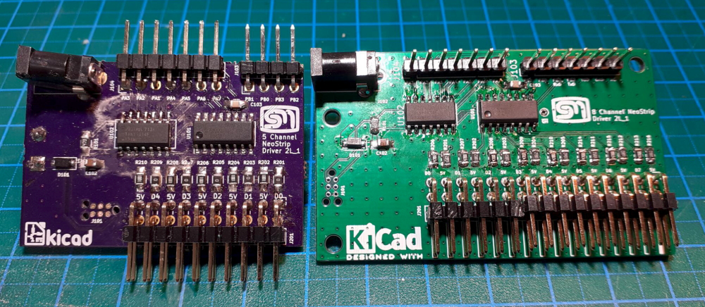
The original board (on the left) only supported five NeoPixel strips. The new one in order to achieve the 8×5 dot matrix font, needed to support eight strips. I used the same project and almost the same layout and implemented the three unused outputs on the shift register. Beyond that, the design is the same as the earlier version.
I took my usual assembly approach and brought things up slowly. Placing only the bare minimum on the board and applying 5V from a lab power supply with the current limited to about 5mA. This helps to identify if there are any shorts without damaging any parts. Unfortunately, this was the case for the first board. I could not identify where the short is on the board so I decided to assemble another. This time testing after each and every part. This time the board did not show any signs of shorts and so I was able to complete the assembly.
Operation
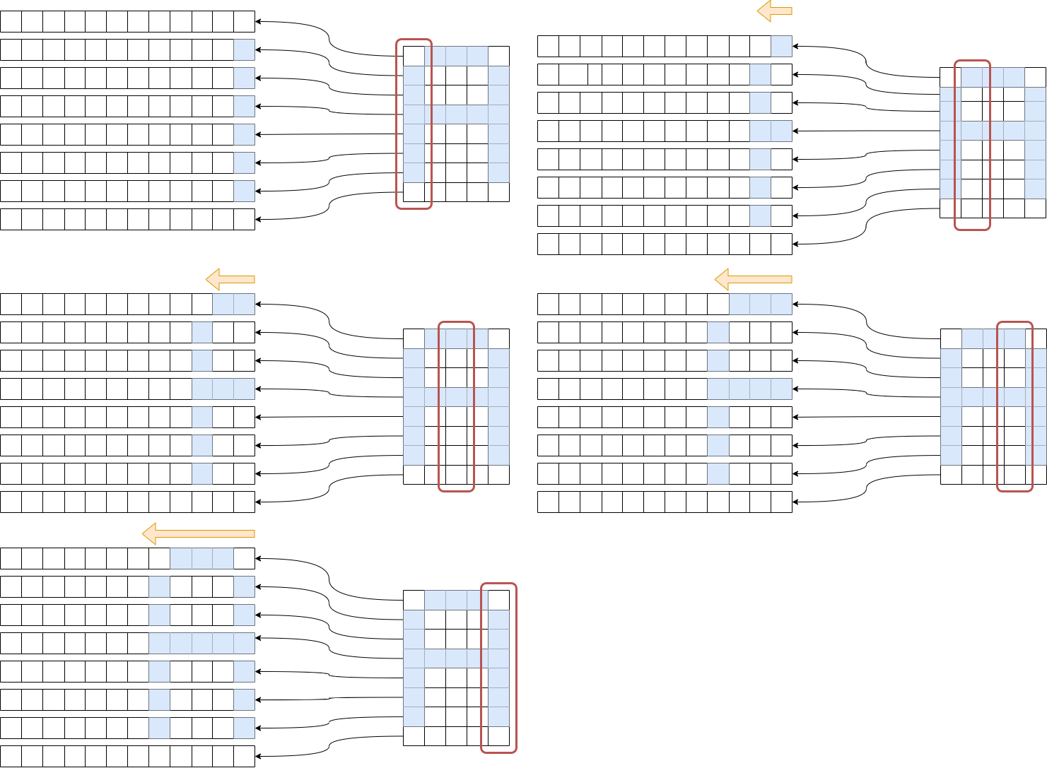
The principle of operation turned out to be simpler than I had thought. The operation is similar to the original design in that there is an array for each NeoPixel strip. The difference here is that there is only one byte required for each pixel instead of three. Each byte would store a colour code that is used to lookup the colour in the colour table. I was able to utilise some of the routines I had previously done to create some of the animation effects on the original project – namely to shift the pixel one place to the left at a time. The pseudocode describes the basic principle of operation.
get the next byte from the font definitionfor each bit in the byte: shift the pixels in the row for the current bit one space to the left. write the current colour code in the element 0 of the strip array that corresponds to the current bit. |
procedure is repeated until the entire character is displayed. Further logic was required to setup for the next character when one is finished and to handle the one column gap between each character.
The diagram attempts to illustrate the process
Conclusion
The full project, officially starting 25 March, 2022 and completed 6 July 2022. It went in a couple of directions before ending up with the final implementation. There were many lessons learned along the way. From the initial concept, I learned about implementing a custom keyboard. Though this was not fruitful for this particular project, I will be able to, no doubt, use this in a future project.
This particular implementation of a text display has taught me about memory optimisation i.e. being able to force the storage of static information into the FLASH instead of the heap. This will be invaluable in future projects also.
I had never really thought of the importance of using a checksum when transferring data. This was an extra complexity I had preferred to avoid. I have some other projects where a checksum is required so I thought it would be interesting to apply a more formal message protocol. I quickly realised the advantages when transferring structured data.
- Having a Frame delimiter made it easy to wait for the correct data to come along.
- Then when the subsequent byte is a data length, I knew how many more bytes to read.
- The checksum at the end confirmed that the data read was in fact correct. This was particularly important during development when the data length was not correct. The message was then rejected with good cause.
I used a similar layout for the new board as I had for the original project. Only after this was implemented and in place that I had a rethink about how this could or even should have been done. The load on the board to the NeoPixel strips will go from the power jack through a 48mil track to the pin headers that connect to the NeoPixel strips. While this is deemed to be adequate for the load, in a subsequent design I would power the NeoPixel strips on an external bus rather than via the PCB.
References
ZAM – Zentrum für Austausch und Machen
Post Corona Stadt (PCS) Project 41 – Textecke
Be warned – the the GitHub repositories are WIP and need a bit of consolidation and cleanup.
Github Repository – 8 channel designs

One thought on “Converting the NeoPixel Driver into a Text Display”