
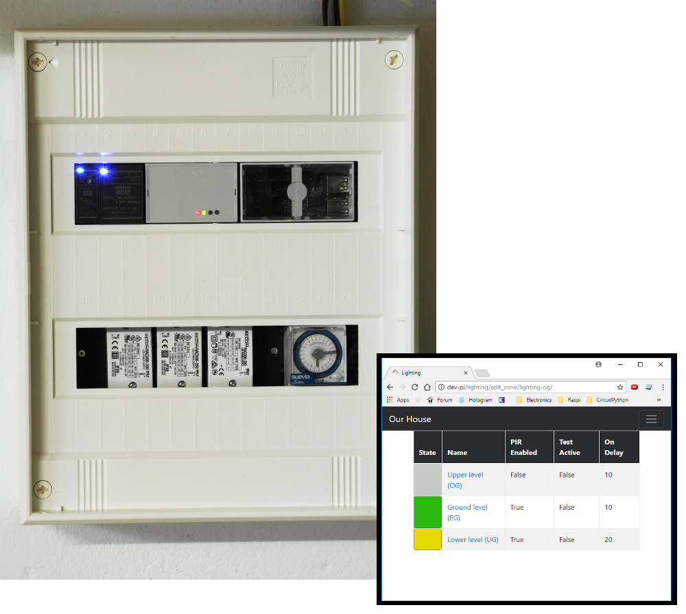
The Timed LED Lighting Control project has been driving the LEDs in our stairwell since 2017. The system is based on two modules. A custom built LED driver, which has been running faultlessly, and a Raspberry Pi + Django based user interface. This year the user interface module died. In this post, I describe the creation of a new user interface module based on the ESP32.
The original user interface was created using Python Django and provided the means to enable or disable the three zones in the stairwell. The system worked faultlessly for five years. The first issue came around 2022 when the menu seemed to disappear – actually the text had became white on white.The library I was using (examples/navbar/navbar.css) is no longer available causing the colours to be corrupt. I let the issue go for a few reasons
- I did not need to use this control page often.
- I knew the page layout and could feel my way around the site and
- I had not done such a great job on making the site maintainable. This was my first Django project and before I had discovered Test-Driven Development with Python.
The next issue appeared in early 2024, we were getting house guests and I wanted to activate the top zone. The user interface site was unavailable! In an attempt to investigate the issue, I could at least log onto the Raspberry Pi. I found that the server was giving a core dump when starting. My assumption there was the SSD card that contained the kernel operating system was corrupt. Satisfied with that assumption, I left things in place with the idea that I would get to it one day. That is until I noticed something quite peculiar. Each month I take a reading of the power usage. Normally the system would use an average of 50Wh per day, which I consider quite high but that was going to be a project for another time. After leaving the Raspberry Pi in place for a month with the Django site not working, the power usage jumped to 113Wh per day! Now it was time to do something. The first thing I did was to remove the Raspberry Pi from the system. The stairwell lighting will still operate without the Django application. Interestingly, the power usage since removing the Raspberry Pi dropped to an average of 5Wh per day.
I realise now that the Django application, while a great choice at the time, did not live up to its full potential. I had plans for other applications but found there was neither any urgency nor necessity. With this in mind I decided against implementing another Raspberry Pi for the user interface but rather employ an ESP32. This would provide a user interface dedicated only to the stairwell lighting. One design requirement is that it should be directly compatible with the Raspberry Pi module. Meaning that no changes should be required to the existing LED driver unit.
Design
There are four main design constraints.
- I2C messages must be compatible with the existing system.
I did not want to make any changes to the existing timed led controller. So the I2C interface can not change. - DIN rail enclosure.
The existing system is mounted in a panel with DIN rails. The new device should also be mounted in such an enclosure. Since I have one on hand left over from the original TL2C project, this constraint was ticked off. The only thing I needed to do was ensure that the PCBs would fit within the enclosure. - The use of the RJ45.
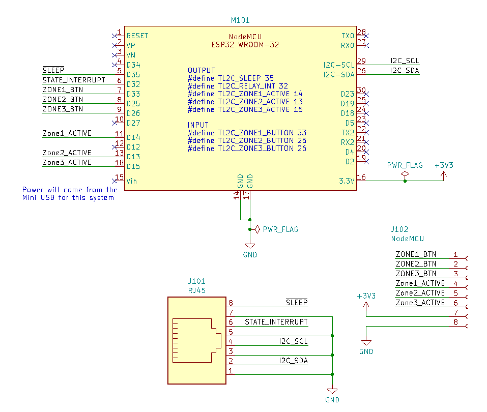
The RJ45 is probably not the best choice for a connector but they are cheap, robust and the cables are shielded. I find this ideal for routing the I2C and GPIO connections from the user interface device to the timed LED controller. - Introduce control buttons with integrated de-bounce circuitry.
I really missed the ability to enable/disable zones from the device itself. The only way this was possible was via a browser. But there are times when I needed change the setting and I did not have the phone/tablet at hand so pressing a button would have been much simpler.
Hardware
Schematic
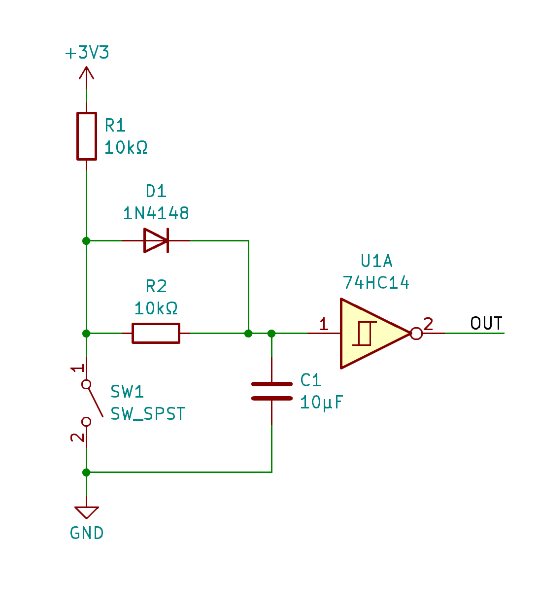
The schematic is relatively simple in that it focuses on the use of a NodeMCU module containing an ESP32 with connection to support I2C and GPIO for the interrupt and proposed sleep signals. The introduction of buttons also brings on the age old issue of de-bounce. Since this project is for me I decided to factor in the additional cost and to mitigate de-bounce with a hardware solution rather than in software. I found a suitable example and proceeded to build it up on bread board to verify the respective values of the components.
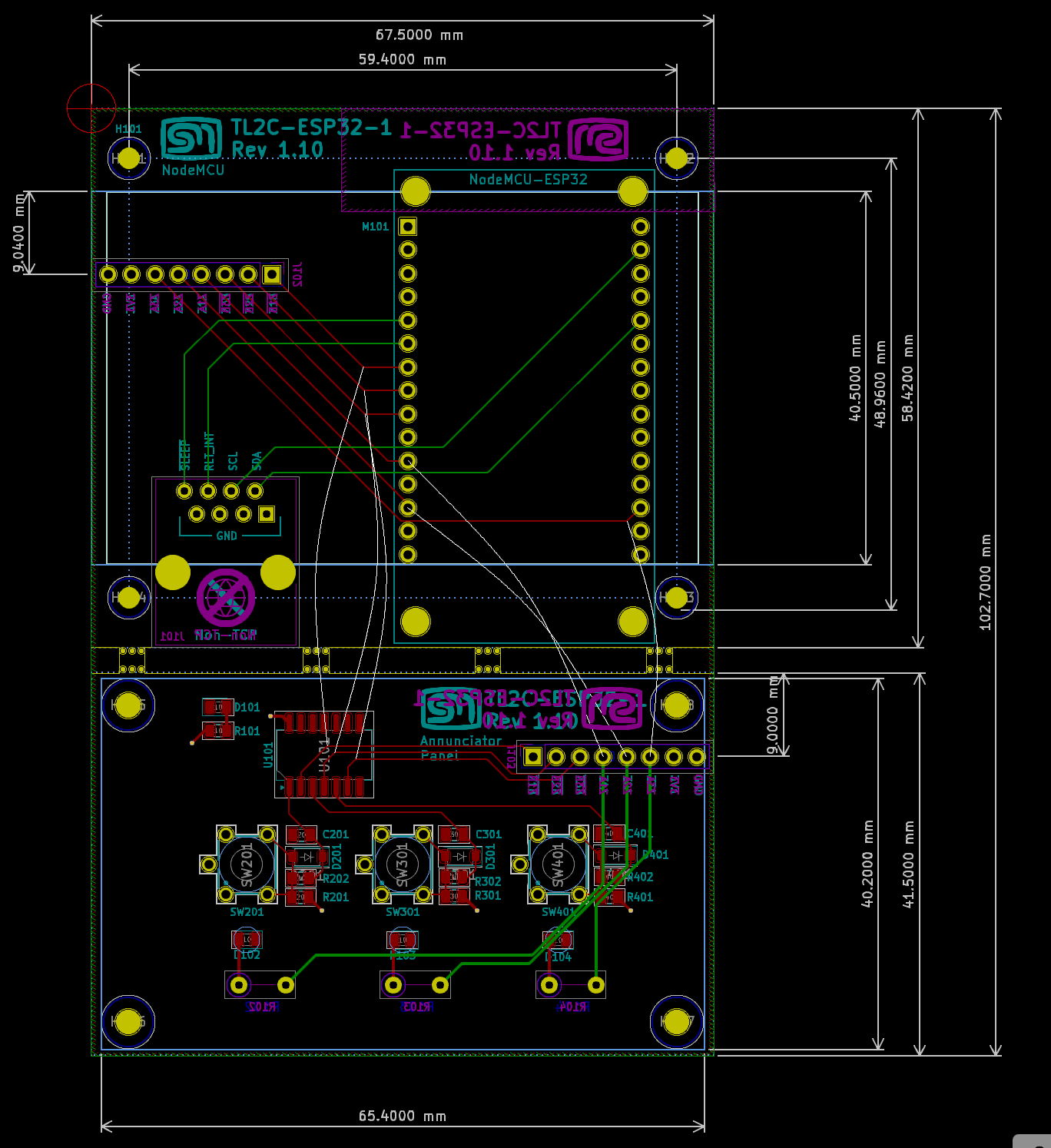
Layout
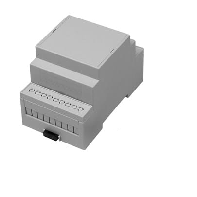
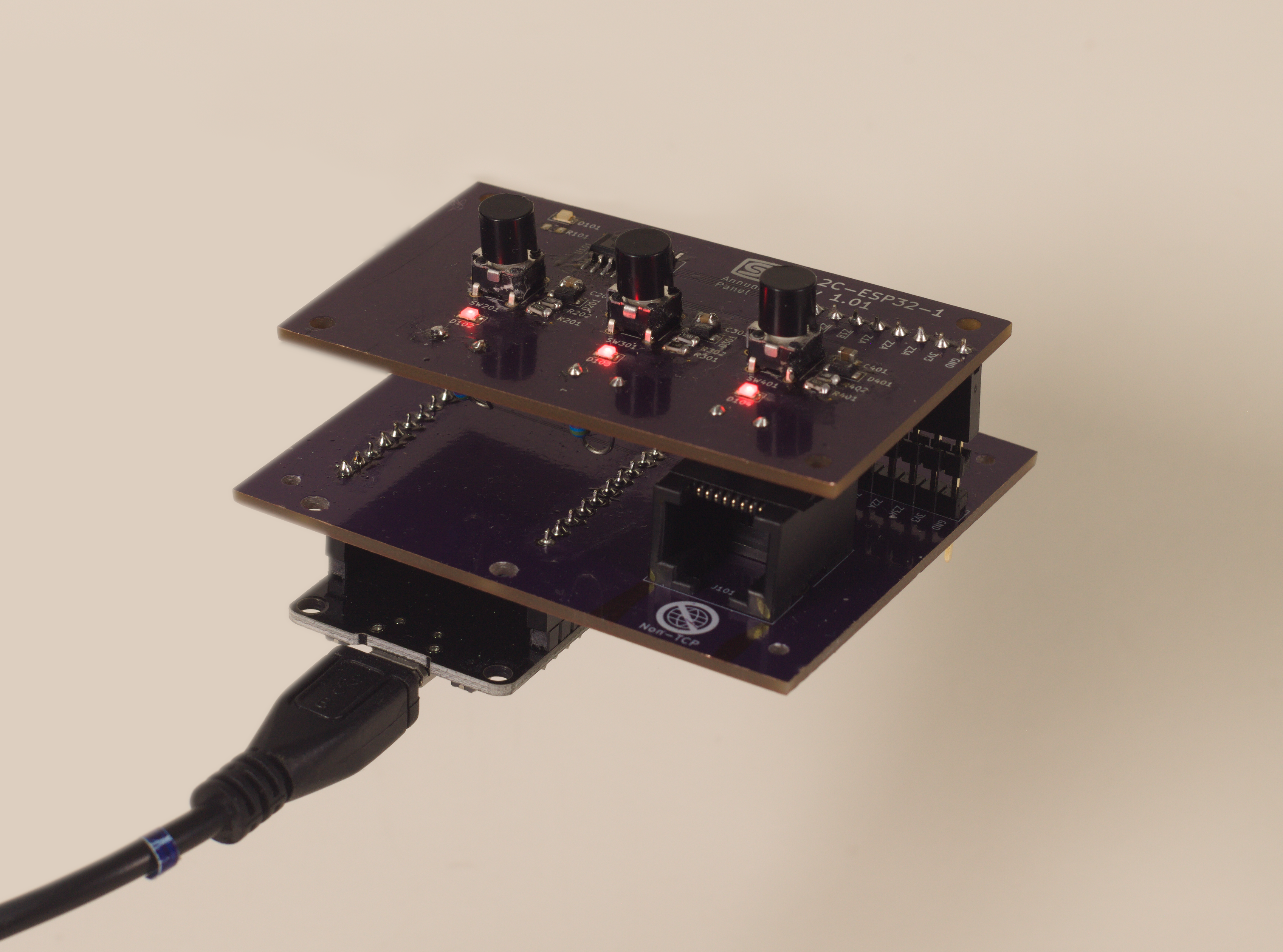
Ideally, the PCB would be a pin-header to accept the NodeMCU module and an RJ45 to connect to the LED control module. But my design constraints stipulated that this needed to fit into a DIN rain compatible enclosure such as the Camdenboss CNMB/3/KIT. In order to achieve this I created the design on two levels: A top board would hold the zone buttons and indicator LEDs. This would be nearer the front panel of the enclosure and would plug into a base board that would contain the NodeMCU module and RJ45 connector.
In order to get things to fit correctly, more time was spent on the mechanical design than the electrical. The layers feature in KiCad proved invaluable. I could set aside user layers to hold rectangles that represented the various mechanical constraints of the enclosure. Using those as a guide, I could then place the components so they would neatly fit within the confines of these constraints. I could verify this using the dimension tool on another layer to display the actual constraint measurements an be sure they match the data sheet of the enclosure. I opted to lay everything out on one PCB and add mouse-bites so that I could seperate them for assembly.
I verified the dimensions of the boards by printing out the boards at 100%, cutting them out and then gluing them to cardboard. That way I could see how they fitted within the enclosure.
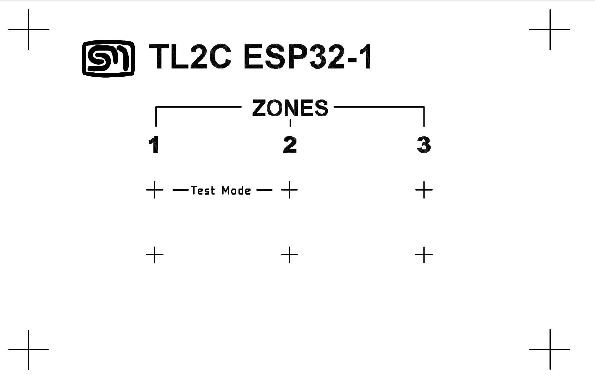
I realised the additional bonus in using layers, I could draw up the artwork for the front panel. I had this printed on some adhesive transparency, cut the holes for the buttons and everything matched up nicely. This also served as a drill template for the front panel.
Firmware
I had a NodeMCU module on hand so I could start on the firmware. Once I had all the communication and GPIO established, I could make appropriate changes to the hardware design. I implement this using the Arduino framework because of library availability and used Microsoft Visual Code and PlatformIO.
On the text display project I used Flash to store static data and wanted to do the same here since the HTML template would not be changing. Here I learned about SPIFFs – The serial file system. This turned out to be quite easy with plenty of examples on the web. It just required a directory structure such as the one shown here. VS Code with PlatformIO provides the ability to build a file system image and load this into the ESP32 flash space.
data
 |
 +- WhiteOnBlack_logo.png
 +- index.html
 +- java.js
 +- jquery-3.7.1.min.js
 +- style.css
The AsyncTCP and ESPAsyncWebServer libraries did most of the heavy lifting in working with SPIFFs and rendering the HTML.
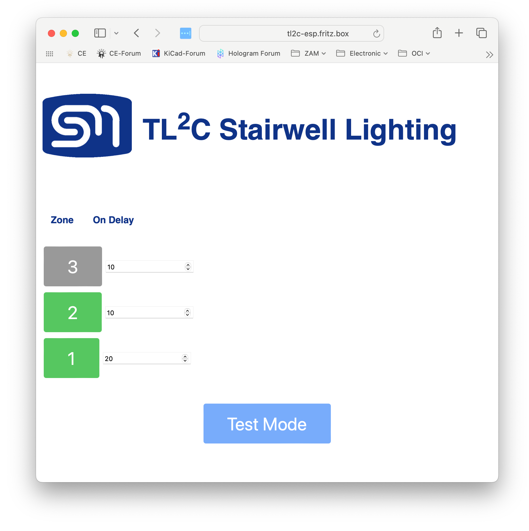
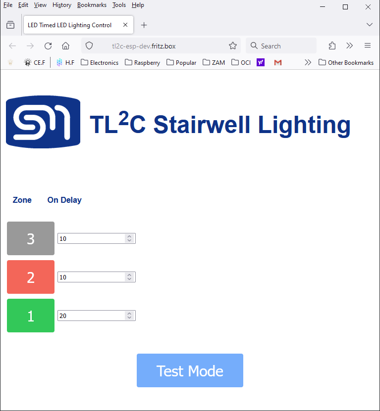
The new user interface was to be somewhat similar to the previous but did not need to be exactly the same. One feature it should still support would be the real-time updates of the page to show the status of the zones and LEDs. The update of the page is done via the JavaScript setInterval function, using the XMLHttpRequest object to query the state of the TL2C every two seconds and then update the page elements using a callback set by the onreadystatechange.
  setInterval(function ( ) {
    var xhttp = new XMLHttpRequest();
    xhttp.onreadystatechange = function() {
      if(this.readyState == 4 && this.status == 200){
        docj = JSON.parse(this.responseText);
        for( jj in docj){
          console.log(docj[jj].zone)
          zone = docj[jj].zone.id
          state = docj[jj].zone.state
          // redButton
          zz = "#zone"+zone+"-button"
          zoneBtn = $(zz);
          if ( state == "ENABLED" )
            newClass = "greenButton";
          else if (state == "ACTIVE")
            newClass = "redButton"
          else
            newClass = "greyButton"
          classes = zoneBtn.attr("class").split(/\s+/)
          currClass = "greyButton"
          for( cc in classes){
            if (classes[cc].endsWith("Button")){
              currClass = classes[cc];
              break;
            }
          }
          if( newClass != currClass)
            zoneBtn.addClass(newClass).removeClass(currClass)
        }
      }
    };
    xhttp.open("GET", "/state", true);
    xhttp.send();
  }, 2000 ) ;
Messages
Because the I2C interface needed to remain the same, I had to remind myself of the messaging protocol I devised for the Timed LED Controller. Luckily I had created a data sheet for my original project and there I could reference the message construction.
There are six registers. Two of the registers are read only and three are read/write. Register 0 (read-only) provides the status information. Registers 1 to 4 define the configuration information (read/write). Register 5 (read only) provides the firmware version.
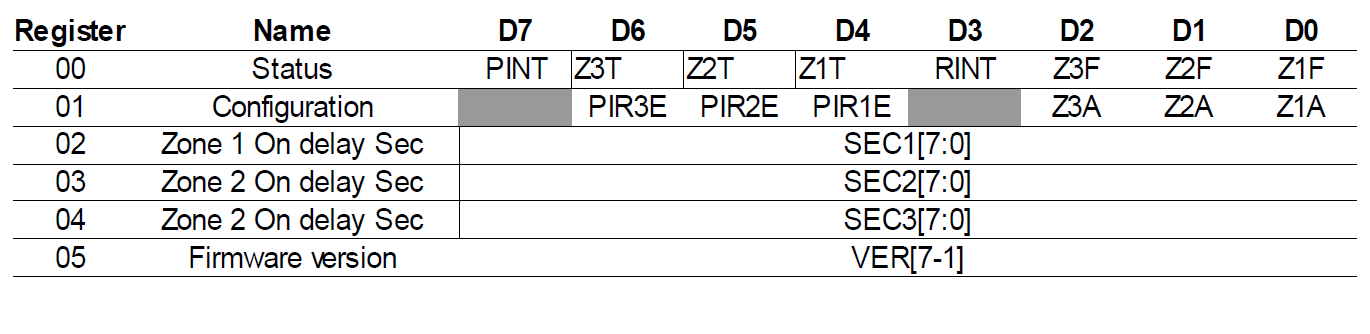
Register 0 – Status
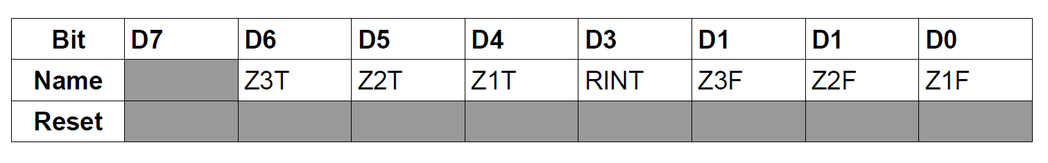
ZnF
The Zone Status Flag indicates if the respective zone is activated i.e. switched on. This flag will remain high for the duration that the zone is activated.
| 0 | Zone off |
| 1 | Zone on |
RINT
The Relay Interrupt Enabled flag indicates that a relay on the LED module has closed. This bit will be
reset on reading the status register. This flag is used to signal to the user interface device that there has been a state change and to up date the internal status cache.
ZnT
This flag will be high for the duration that a particular zone has its Test Configuration flag
enabled.
| 0 | Zone Test active. |
| 1 | Zone Test inactive. |
Register 1 – Configuration
Reading this register will return the current state of the zone configuration. Writing to this
register will configure the respective zones as described in the sections below.
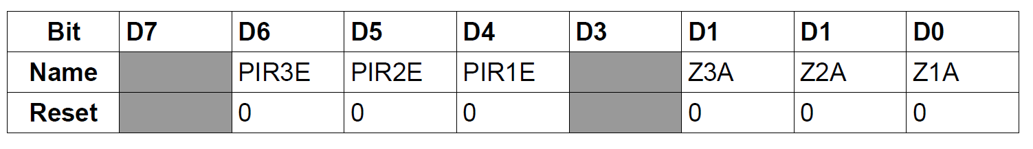
ZnA – Zone n Activation (Test) Flag
The activation bits will turn on the respective LED zone permanently with no
regard to the configurations of the Zone On Delay settings. Setting the respective bits High
(1) will activate the LED zone. This will also set the respective bit in the Zone Status Flag
register. Setting the bit Low (0) will switch off the LED zone. This will also affect the ZxT
flags in the status register.
PIRnE – PIR13 n Enable Flag
The PIR13 Enable Flag will indicate if the controller will react to a signal from the
respective PIR13 motion detector. When the flag is set High (1), signals from the PIR13
will be enabled and will cause the LED zone to be switched on for the amount of time as
configured in the respective Zone On Delay Register. Setting the flag to Low (0) will
disable the signal from the PIR13 module.
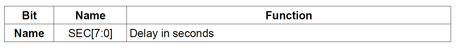
Register 2 – 4 – Zone n Delay
Reading this register will return the current delay time for the respective zone. Writing to
this register will configure the delay for the next time the zone is activated.
The Zone Delay is the number of seconds the LED zone should be activated for when it
receives a signal from the respective PIR13 and the PIR13 is enabled for that zone. This
register has no impact when the Zone Activation (test) Flag is enabled. The value provided is
expected to be an unsigned 8bit value. This provides a maximum delay of 255 seconds i.e.
4.25 minutes.
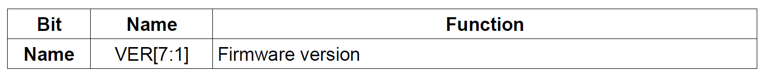
Register 5 – Firmware Version
This is a read-only register to return an unsigned eight bit value to indicate the firmware
version.
Diagnostics Logging
As with a recent project LPS-1, I introduced a set of macros to provide a standard way to log diagnostics and more importantly, to be able to disable it when no longer needed since access to the USART would not be available once the device was installed. The header file logging.h was taken from the LPS-1 and refactored for the Arduino framework.
#if defined(LOGGER_LEVEL) && LOGGER_LEVEL > LOGGER_LEVEL_INFO
    #define LOG_DEBUG(args...)  { Serial.print("DEBUG: "); Serial.print(args); }
    #define LOG_DEBUG_F(args...) { Serial.print("DEBUG: "); Serial.printf(args); }
    #define LOG_DEBUG_LN(args...) { Serial.print("DEBUG: "); Serial.println(args); }
#else
    #define LOG_DEBUG(args...)
    #define LOG_DEBUG_F(args...)
    #define LOG_DEBUG_LN(args...)
#endif
Assembly and Testing
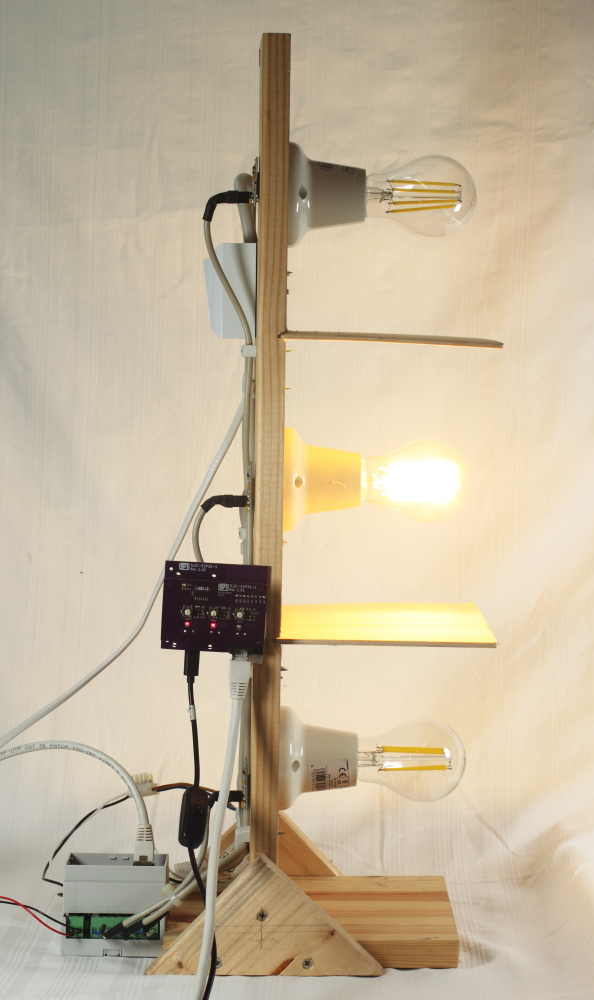
I was able to use the test harness that I had created for the original project. It is fitted with three sets of PR13 sensors and lamps. A baffle between each lamp/PR13 set simulates the three zones I want to control. I also had a spare TL2C LED controller unit that was used in the development of the original project. With this configuration I could easily test the behavior of the User Interface as it reacted to the TL2C events.
As mentioned in the design constraints, I wanted to provide de-bounce in hardware rather than in firmware so that the so firmware could be dedicated to handling the I2C events and rendering the user interface. The circuitry for this was placed a board that would connect to the board containing the NodeMCU, so that the buttons and indicator LEDs could be exposed and accessible through the front panel.
Usage
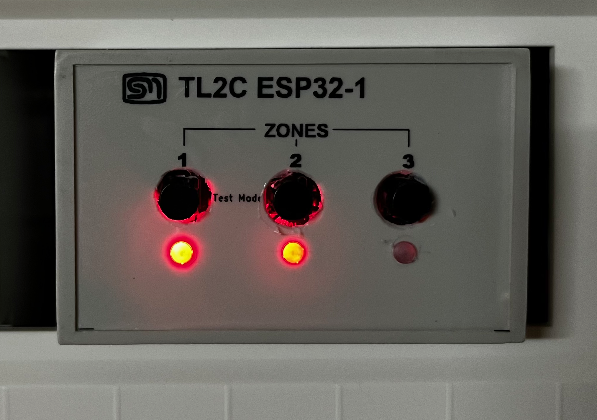
The new module plugged strait back in to where the old one was taken. I only needed to connect the RJ45 and the USB mini for the power supply and it was already in service. Just like on the browser based user interface, it is possible to activate each zone in turn or place the system in to a test mode.
On start up, the device will read the state of the LED driver and display the state on the LEDs. If the zone is enabled, the indicator LEDs will illuminate. Pressing a button will toggle the the zone either on or off. A short press on buttons 1 and 2 will put the system into a test mode. This is where all the LEDs on all the zone will be activated regardless if that zone is enabled or not. A short press on the zone 1 and 2 buttons again will take the system out of test mode.
Conclusion
The transition from a Raspberry Pi with a Django-based interface to an ESP32 has not only resolved the issues I faced but also significantly improved the efficiency of the Timed LED Lighting Control system. I believe the new design is more streamlined and power-efficient, reducing the power consumption from 50Wh per day to about 20Wh per day. Additionally, the ESP32 provides a more responsive and user-friendly interface, making it easier to manage the stairwell lighting zones with either browser based or actual push button controls.
This project has been a great learning experience, from both the hardware and firmware aspects. In KiCad, I was able to take advantage of the layers to help with the mechanical design. I was also able to learn about SPIFFs and just working with the EPS32 in general. I believe using this configuration has made the system a little more maintainable.
What’s next?
Though the system is installed and working well, there is always room for improvement. I had always envisaged a type of astro-time configuration for the system i.e. activating at sun-down. With the ESP32 being able to reach out to the internet for the current time, I see this feature being very possible. To compliment this feature, I would like to introduce the ability to put the LED driver module to sleep when it is not required. i.e. during the daylight ours. The ATtiny20 firmware has almost reached its limit. I would need to update this to an MCU with a little more flash space.
An additional enhancement would be to introduce a admin or configuration page to the browser based user interface. Currently the WIFI configuration is hard coded to the home WIFI. This will be a problem if that configuration should change. I had drafted up how this could be introduced but decided to make this as an enhancement.
