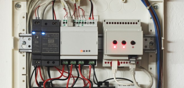
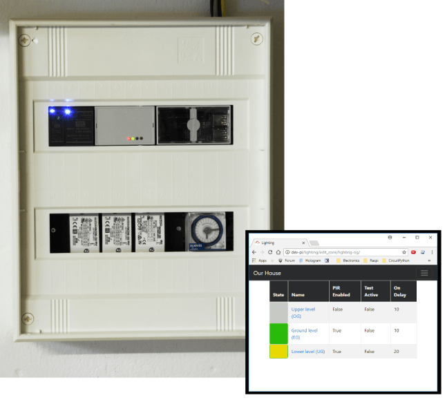
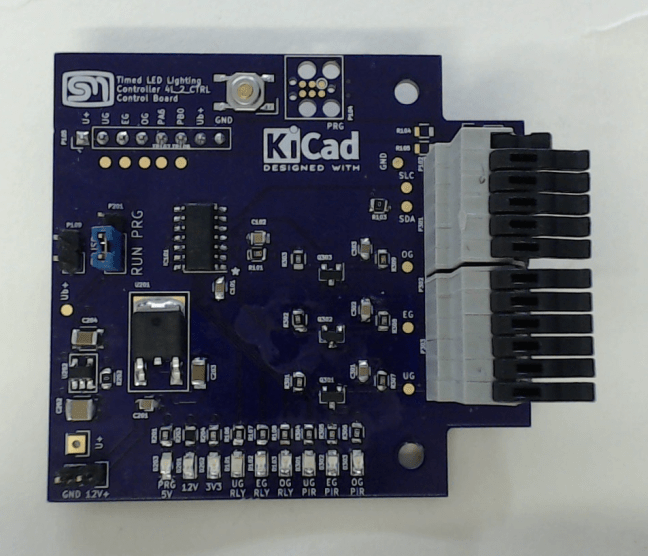
Wrapping up the Timed LED Lighting Controller Project

Introduction

I have written about the Timed LED Lighting Controller in previous posts. Starting with the original entry “Stairwell Foot Lighting System. In this entry I will be wrapping up the project and describing the change of direction from the initial design and layout. There may be a bit of overlap but it will be minimal as the project took a small deviation along the way.

Continue reading Wrapping up the Timed LED Lighting Controller Project

From Proof of Concept to Prototype

In the last entry for the Timed LED Lighting Controller, I realised that there are no working examples of an I²C driver for the ATtiny20. I then had to work through the data sheet to implement my own. With that done, I could then start on the application firmware and get the board really working. So this is where my proof of concept becomes the prototype.

Continue reading From Proof of Concept to Prototype

“Mocking” – Minimising Risk

In the last post  for the Timed LED Lighting Controller, I had figured out the circuit and a basic layout and approach that I was happy with. That is to separate the hazardous voltage from the control circuitry by putting it on a separate board. But still, this was not enough. I need to assemble this in a case. No hazardous voltage is allowed to be exposed. The idea of printing a case is attractive but I don’t really want to loose focus of this project. I can always reserve the printed case for revision 2.

Continue reading “Mocking” – Minimising Risk

Timed LED Lighting Control – Design

From Logical to Physical

Before I could start to translate the block diagram into KiCad, I needed to be sure about some of the parts I will be using. I want to reuse what I already have installed, so the motion detection module is already a given, along with the LED drivers. The micro controller needs three output pins, three input pins, I2C support as well as the pins for a program header. Since I have worked with Atmel in the clock project and therefore have the tool set I need, I decided for the ATTiny20. The only part I needed to look around for was the relays. As per the block diagram, I decided that the coil would be 12V and the switching contact should be for 240V AC RMS. For the moment I have settled on the JW1AFSN12F from Panasonic.

Translating the block diagrams to KiCad was fairly straight forward. The resulting KiCad diagram pretty much matches the block diagram in so much as the power system, relay driver and the PIR13 interface are modelled in their own sheet. In order to help to keep the 240VAC side separated from the Extra Low Voltage control section as much as possible, I opted to try for a stacked board layout. The two boards will be connected via a pin header and socket (P105 and P107). To simplify this layout I opted to utilise the different notations for the Ground plains. GND for the Extra Low Voltage board and GNDA for the Low Voltage Board.

tl2c-sheet1-main

tl2c-sheet2-powersystemThe Power System comprises of two LDO regulators. One for 12Volt and the other for the 3.3Volt supply. It is expected that the plug pack adapter will probably deliver about 14V – if not, I can always drop the 12V regulator out of the design. It is only provided for extra regulation. As already indicated in the previous post, the 12Volt supply is for the PIR13 modules and relays. The PIR13 modules can handle from 5 to 24Volts as a supply. Because of the distance of the cabling, any voltage drop should be within tolerance. The Micro Controller and therefore the signal lines such as for the I²C bus will be at 3V3 which is compatible with the Raspberry Pi removing the need for any level shifting. The ATTiny20 shares the pins for the I²C bus and SPI bus. At the moment, I have separated these with a couple of resistors as recommended in another article. I have my reservations about this and may yet change this over to a set of jumpers or even a double pole switch.

tl2c-sheet3-pir13

The signal from the PIR13 is open collector. To avoid having a direct connection between the ATTiny20 and the PIR13 modules, I will be installing some MOSFETs I already have from another project.

tl2c-sheet4-led

I am using the same MOSFETs to drive the relays. As a part of this initial design and a lesson learned in previous projects and Contextual Electronics, I will be including test points and indicator LEDs. An additional lesson learned is to not leave any spare GPIO pins unconnected. These can come in handy and for that reason I have even broken them out onto a pin header. I don’t have to populated the pull-down resistors nor the pin headers for these. But they are provided for if I need it.

Laying it out

I originally envisage the layout as a two piece board that will be separated after assembly. The first attempt was a two layer board and was not nice at all, so I shifted the design to a four layer board. This has pushed the price up enormously. The tip came from Chris Gammell to separate the two sections into their own layouts. One as a two layer board (the 240Volt AC section) and the other as four layer. This has reduced the overall cost significantly and now enables to be enlarge them enough for mounting holes and still be cheaper than the original full layout. The trick with this is how to model this in KiCad. I have tried out my own workflow for this:

  • Model the two boards as needed in the Master Layout PCB as 4-layer. This enables matching the mounting holes and pin-headers without having to swap between layouts
  • At the command prompt, copy the Master Layout PCB twice. Once for the 240V board and the other for the Extra Low Voltage (ELV) board.
  • In each new layout file, delete the section that is not needed and re-adjust, if needed the board layout graphics.
    • Adjust the layers for the 240V board from 4-layers to 2-layers.

tl2c-initiallayout
“Master Layout” Both boards side by side

Design considerations and constraints

I am reasonable happy with this initial cut of the layout. However, I am not quite ready to send this off to OSH Park. This project and board contains an element I have not worked with before – Hazardous Voltage. This can not be under estimated. One aspect to this is to separate the Low Voltage (LV to ELV boards onto their own. There is still the question of Clearance and Creepage to consider on the LV board. There are a number of very good essays written some with calculators

Calculators
Trace Width
creepage.com
PCB Trace Spacing
Essays
Creepage and Clearance
Clearance and Creepage Rules for PCB Assembly

So I have a bit of a quandary. I don’t want to send off the board for manufacturing before I have sorted out the safety aspects of the design first. I could send it off as-is but if there is a specific requirement I need to meet, I will have to request another. I can, however, make a compromise. With the tip for splitting out the boards as separate PCB files, I can send off the order for the four layer part and leave the two layer, LV board for further consideration. In the mean time, I can bring up and test the control board since the relays either are not needed for the proof of concept or can be simply wired in for basic testing.

At the moment, I have a small uncertainty about the housing and the terminal blocks. It is much easier for me to choose or to know what to look for when I have some actual samples in my hand. So I have ordered a couple of samples to get a better idea of these parts. It is tempting to consider to print the case. However, this would push out the project and shift the focus to a 3d Printing project. I would prefer to keep on track with the Timed LED Lighting Control hardware and firmware.

In the next post, I hope to have the casing and terminal blocks worked out which means that the board will be ready for fabrication. So hopefully then I will be able to talk about bringing the board up.

Stairwell Foot Lighting System

When getting back into electronics, one of the projects I had in mind was to revamp our stairwell lighting system. In 2010, we renovated our stairwell. I took the opportunity to design in a foot-lighting system that was motion controlled. It has worked faultlessly for the last six years. But who can stop at revision 1.0 when there is so much more can be done? This entry is about working out a new stair well foot lighting controller.

Fixing What is Not Broken

If it has worked faultlessly for six years, then what is there to fix? The basic driver was the size of the original solution. Like the doorbell project, the original was put together with what I could obtain with what I understood at the time. I have no regrets about that and would take that approach again since it solved the problem. However, since day-one, I had always had it in mind that I would like to rework this with my own Micro-Controller solution. Now with what I have learned in nearly two years, it’s time.

img_0304s2

This initial solution comprised of an electro mechanical timer – that I have to manually set for Summer time and Winter time. It has three PIR13 modules from ELV as the motion detection sensors and three sets of PIR13 timers (also from ELV but now obsolete) connected to a LED driver from SLV that can drive up to eight high power LEDs each. In my system, I have only a maximum of four in each bank.

Initial Ideas – to the big picture

lcu1sI had envisaged using a small embedded device with an inbuilt touch display. This device the LCU1 was released by EQ3 through ELV. It has a tool set for UI development with direct interfacing to analogue inputs and four relays. I was attracted to this device because of the the embedded Linux and the size. I imagined having this positioned in place of the existing control system. Instead of the mechanical timer, the timing would be internal and possibly supported by “Astro” calculation. Any additional changes to the set up could be done by using the touch screen. I also have the thought that this could be eventually expanded as a burglar alarm. I had got as far as a rudimentary graphical user interface. There was still a lot to sort out with regard to interfacing with the motion sensors and eventually the connection to LED foot lighting. This is where I seemed to reach my limit and the project was put in a drawer. …In the mean time, the Raspberry Pi arrived!

The Raspberry Pi, with its huge support network, inspires and enables new ideas to be realised. After EQ3 brought out their Homematic transponder for Raspberry Pi, I was inspired to get this project back on the table.  In our house we have the Homematic system from EQ3. This is a Home Automation system that has a rich set of sensors and actuators using a bi-direction wireless protocol. It also has provision for a wired solution too, for larger, more complex installations. The beauty of this system is that it can be built upon. Starting only with, say, one heater regulator, then perhaps adding a wall thermostat and eventually adding in the Central Control Unit (CCU) to handle more complex relationships between the sensors and actuators. For a couple of years now EQ3 released their CCU2 firmware for Raspberry Pi. This now opens an exciting new world of possibilities that goes beyond a simple foot lighting controller

I realised that even though the touch display would be a cute feature, it was not actually essential to the solution. From a user point of view, any changes to the system would be better made by simply picking up a tablet and making the changes over a browser rather than having to go down into the basement each time – which is how changes are currently made.

So the plan is that the Raspberry Pi will be taking over the operation of the CCU2 with the lighting controller connected to the Raspberry Pi via the I²C bus and a Web User Interface enabling remote control of the lighting system and Homematic installation. I need to stress that I have no big interest in accessing this outside the home. The possibility is still there with the Raspberry Pi as the “back bone”.

smart-home-context

I modelled the complete set of ideas as a SysML block “context” diagram. The idea here is that the new Lighting Controller is type of I²C device connected to a Home Server. The Home Server is an abstract description that is modelled as one or possibly more Raspberry Pis. The CCU2 and a web server is envisaged to run on the Pi.

The diagram below is similar to the context diagram but only contains the components relevant to the stairwell foot lighting. Taking this one level further I modelled the internal block diagram for Lighting Controller to start to explore the different power domains that the system will have to deal with. I have decided from the start that I will be trying to work solely with 3.3Volts and not the 5V/3V3 mix that I had with the Clock Project. However, I have found it prudent that 3V3 is suitable for micro controller but 12V is probably better for driving the relays and the motion detectors.

lighting-controller-block-diagram

lighting-controller-internal-block-diagram

The Timed LED Lighting Controller (TL2C) has four basic parts. A Power System a Controller , three banks of LEDs including their drivers (I will be still using the drives from SLV) and three motion detectors (PIR13 modules).

The original intention for the Power System was to pass through 240V to the LED drivers and also provide the 3V3 for the controller and 12V for the relays.

lighting-power-system

A short discussion with my tutor, Chris Gammell of Contextual Electronics hinted that the design of an off-line power converter would probably shift the focus of this project to power supply design. This could certainly be tackled but maybe in parallel or at a later stage. It would be quicker to simply use a “Wall Wart” for the 240V to 12V conversion. A simple LDO  regulator can then be used for the 12V to 3V3 conversion.

As the larger context block diagram indicates, there will be more components to this final project than just a single micro controlled device. I will need to move the existing CCU2 set up I have to the Raspberry Pi, build some type of Web User Interface to be able to interface and configure the Stairwell Foot Lighting system and finally see if it is possible to integrate the astro timer of the CCU2 to the foot lighting system. My initial thought is through the XML-API offered by the CCU2. This will be confirmed in a future post.

To be honest, I am not sure how the web interface will work between the lighting controller and the Homematic CCU2. I figure I will let that piece evolve as I learn more about website deign, CGI and Python or what other scripting language I will choose to interface the I²C bus with Web front end.

In the next entry, I will be talking about the design I will come up with for the Timed LED Lighting Controller and the parts selected.