
I have mentioned about the re-working of an old alarm clock. In this post, I will be kicking the project off and introducing my efforts to model the requirements and project organisation in SysML. I will be using Systems Architect from Sparx Systems.
Project Organisation
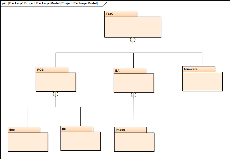
The project organisation shows the directory structure of the project in the form of a package diagram. The project is organised into three areas. One for the Enterprise Architect repository, on for the PCB or KiCad files and a third area to contain the firmware source code. This project is also available from the GitHub repository.
Requirements
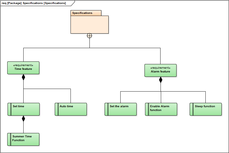
In order to organise and document the features and functions for the project, a list of definitive requirements are first modelled. They enable the features and functions to be created and considered in the context of these requirements to ensure that the final device will contain all the correct features and that they will function in an expected way. In reality, this diagram is not enough. Each of the requirement boxes contain further detail about their meaning. The basic requirements are clear, even trivial. The clock should have a Time Feature and an Alarm Feature. Under the Time Feature, the user should be able to set the time when not in auto-time mode. The user should also have a simple way to set summer/winter time when in manual-mode.
Under the Alarm Feature, the user should be able to set the alarm time, enable and disable the alarm and operate a sleep function when the alarm is sounded.
Block Diagram
The main block diagram contains the overview of the interconnecting modules of the whole clock system. It shows the power system that should deliver at least two levels – Vdd and Vb. These represent the +5V and 3.3V respectively to source the controller and the Real Time Clock module (RTF-DCF77). The RTF-DCF77 is a real time clock module that also incorporates capability to receive the DCF77 signal that is transmitted in Germany. This module has the capability of communicating with UART, I2C and SPI. The block diagram shows that communication will be established through a SPI bus. Three additional interrupts will be also implemented. The periodic interrupt (one second intervals), the DCF77 receipt interrupt and the alarm interrupt.
The micro controller (ATMega88) will have inputs from the device casing for the control buttons – implemented through InputPort D. The SPI bus will be implemented via the pins on the ATMega88 set side for this purpose i.e. Port B. An additional port will be used as the chip select 2 (/SS2) for the display module. Port C will be used to receive the interrupts from the RTF-DCF77 module.
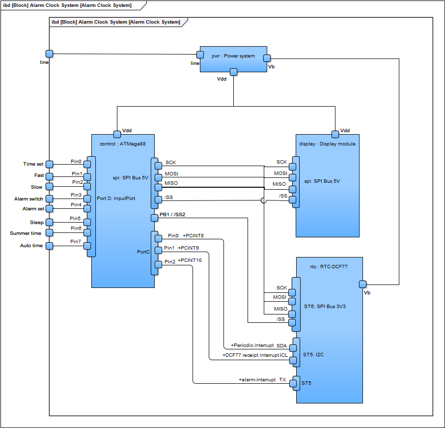
The SysML ports modelled as the SPI on the micro controller, the RTC-DCF77 and display modules are each of two types. A 5V version and a 3.3V version. The nested ports on the RTC-DCF77 are to also implement a level shifter to convert the 5V down to 3.3V. It is difficult to encapsulate this information without cluttering the diagram. What also seems a little unclear is the use of ST5 and ST6 nomenclature. These are the pin header labels on the actual physical module. Further information that would also be useful is the actual pin number on the pin header. I also figure that detail can wait for the schematic in KiCad.
System Interaction
Before I close this blog, I need to resist the urge to jump right into KiCad (and start doing some real work), to at least present a model regarding the internal interaction of the device. I believe this where the most time can be lost in SysML. The examples presented in the reference books are usually well contrived. Trying to fit the concepts into a simple case proves to be challenging. The idea is to model some behaviour behind the system block, parts and even use cases. The diagram presented below is a full state machine diagram for the alarm clock. This model was actually made some time ago and to save time, this time around, decided to import it into the new model since it is still a very close fit. There are some things missing like the interaction of the real time clock and enabling and disabling the alarm. I will add these in due time.
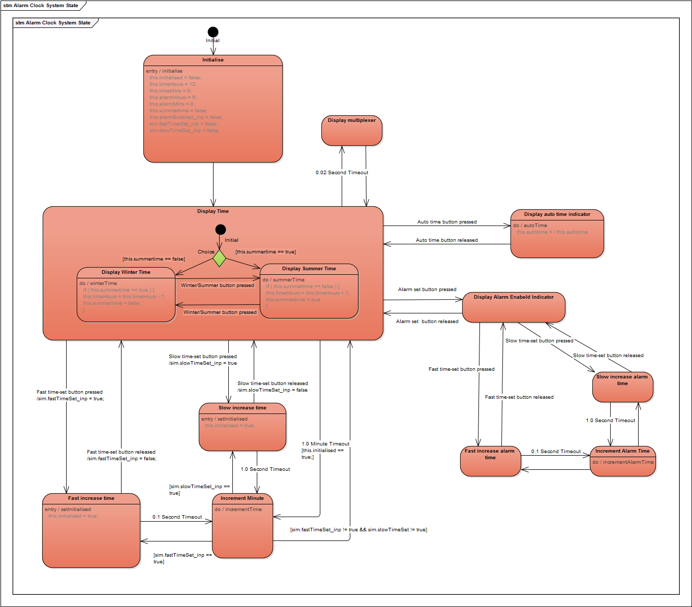
Under Systems Architect, this model can be simulated and you are able to see the execution through the various states when the various triggers are applied. This is another reason why a lot of time can be lost in this stage – you forget that the purpose is to model the behaviour and time is spent just getting the simulation working – but its fun. Since I already had this working model, I decided to import it and save that time.
The basic operation is to display the time. This will either be standard time or summer time. The rest of the model shows the interaction when various events are triggered, such as the time set button pressed and released.
Wrap-up
The SysUML model for the Alarm Clock project is by no means complete. Though I think I have provided enough at this stage for a project of this magnitude. The other models and definitions can and probably will be added as I move on with other aspects of the project. I am keen to get into the real hardware side and start to get things happening. In reflection I have to admit some things have come out in the exercise of modelling this in SysUML that I am grateful for.
- I have a clear list of modules with clear requirements to develop and integrate into the final solution
- Power system to deliver +5V and 3.3V
- Display module
- with indicators for auto-time and alarm enabled.
- SPI capable
- Real time clock. This is a given since I will be using the RTC-DCF77.
- A clear allocation of the ports and interrupts of the micro controller before I start connecting and coding. This means I can start exploring the firmware already.
The state machine certainly needs some more re-work but this is enough for the first-cut.
Next Steps
The next steps will actually be to start working with KiCad. I don’t believe that a project of this size needs to be documented to death when the direction and requirements are known. As I said, I may well go back and correct and add some more diagrams where things are unclear and need further thinking/clarification. Research is also required for the display module. I do not have anything off-the-shelf for this so may have to consider to develop my own.

These are really impressive ideas in regarding blogging.
You have touched some fastidious things here. Any way keep up
wrinting.
LikeLike