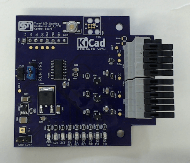
Back to Blinky

In this post I describe the trials an tribulations of bringing up my Timed LED Lighting Controller and how I went about implementing my first I²C Slave Driver for the ATTiny20. I was keen to receive the boards for the Timed LED Lighting controller to know if they would fit in the chosen housing. The … Continue reading Back to Blinky

“Mocking” – Minimising Risk

In the last post  for the Timed LED Lighting Controller, I had figured out the circuit and a basic layout and approach that I was happy with. That is to separate the hazardous voltage from the control circuitry by putting it on a separate board. But still, this was not enough. I need to assemble … Continue reading “Mocking” – Minimising Risk

Timed LED Lighting Control – Design

From Logical to Physical Before I could start to translate the block diagram into KiCad, I needed to be sure about some of the parts I will be using. I want to reuse what I already have installed, so the motion detection module is already a given, along with the LED drivers. The micro controller needs three … Continue reading Timed LED Lighting Control – Design

Stairwell Foot Lighting System

When getting back into electronics, one of the projects I had in mind was to revamp our stairwell lighting system. In 2010, we renovated our stairwell. I took the opportunity to design in a foot-lighting system that was motion controlled. It has worked faultlessly for the last six years. But who can stop at revision … Continue reading Stairwell Foot Lighting System

Wrapping up the Alarm Clock Project

It has been a long while since the last post. Amongst other things, the clock has been a work-in-progress. Each time I made some progress, I found some new reason to create a revision. The initial revisions where based on issues and oversights. I am finding that as the project matures, the nature of the … Continue reading Wrapping up the Alarm Clock Project

Further testing the μController Display Module

In the last post, I was able to get the μController version of the display module working with a basic test routine that proved that 1. the controller could be programmed and 2. the display was being driven correctly. The next stage is to flesh this out to replicate the MAX2771 API. The purpose here … Continue reading Further testing the μController Display Module

Powering up the μController Display Module

In the last post, I set up the infrastructure on my newly configured PC to make sure that it can at least communicate and program a chip. I needed to do this before jumping in and starting to program the μControll based display module to minimise the number of issues to be encountered. Initial Check … Continue reading Powering up the μController Display Module