Playing with some animations of the single LEDs strip of my NeoPixel board was nice but the thoughts soon come to mind: “It would look better if there were more strips”, “…if there were more strips, how could they be coordinated”, to “Could I still use the ATiny1614?”.
To take this project further, I considered several Ideas which lead me to using a Shift Register to help with “addressing” the various “channels”. Once the data output lines are set, the Enable pin could be used to pass the colour data to the LED strips. The diagram below illustrates an “address” of 0x16, setting the outputs B, C and E. The signal presented on the enable pin is then transferred to the selected outputs. Note that the Enable signal needs to be inverted to obtain the correct signal on the respective outputs.
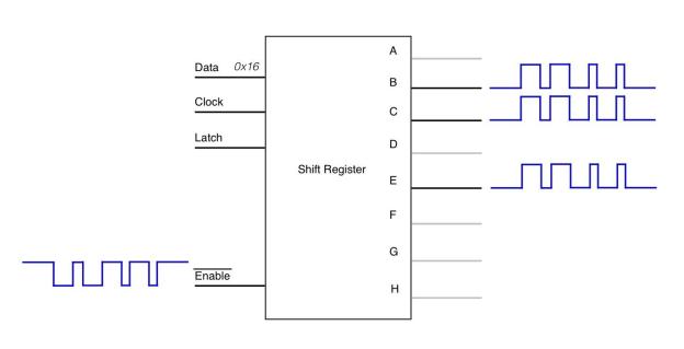
Schematic
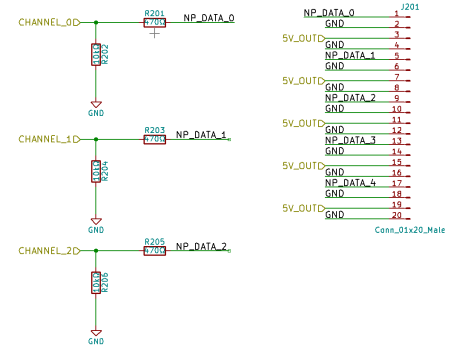
The main difference to the first NeoPixel project is the addition of the 74HC595 Shift Register. As described above, the microcontroller will send a value to the Shift Register which will enable its respective output pins. These are in turn, connected to the data lines of the LED Strips. The microcontroller would then drive the enable pin of the Shift Register to pass the colour information to the LED strips connected to the shift register output pins
Even though the concept could support eight strips, for the purpose of the prototype and keeping the board to a reasonable size, I opted to connect up only five outputs. The data sheet for the 74HC595 indicates that the outputs are tri-state when in a disabled state. Therefore, to ensure a true Low state, I had to tie the the output lines down with 10kΩ resistors. I also maintained the recommendation from Adafruit to add a 470Ω resistor in series with the LED strip data line.
.
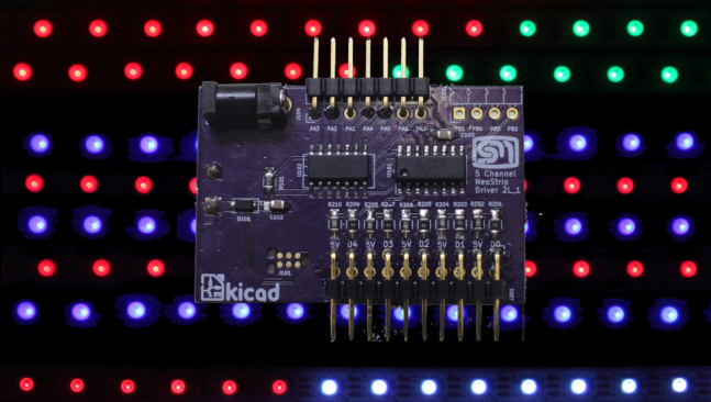
The power supply is as per the original version. A 5V supply is provided through a 3mm Power Jack for a solid connection. The layout, again, places the recommended 1000μF capacitor on the bottom side. A diode is placed in line with Vcc to offer some rudimentary reverse polarity protection for the microcontroller.
Programming is done through the UPD one wire protocol. I had been through all that with the first version so I was not expecting any surprises.
Assembly and Testing
The assembly was straight forward having selected parts that I am used to working with i.e. 0805 and SOIC. KiCad offers predefined “Hand Solder” footprints for some parts, which are just a bit bigger than the normal.
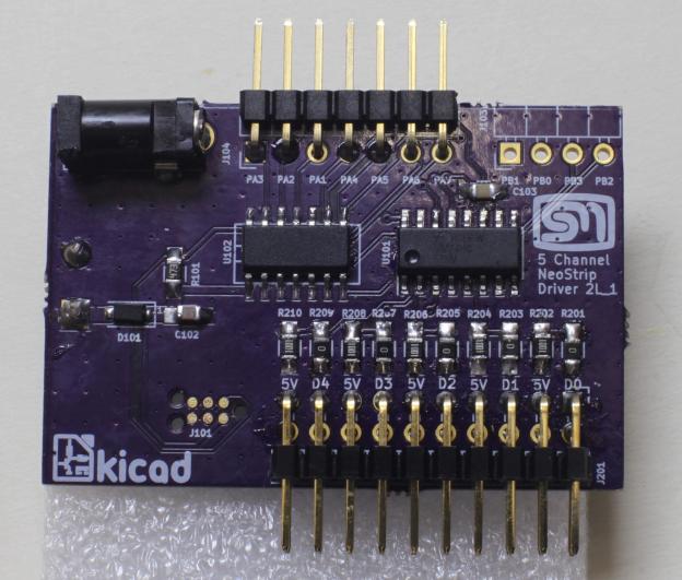
Bringing the board up and testing provided a few challenges. First the usual test on the Lab power supply before adding some of the through hole parts to be sure the board is OK and contains no shorts. I then the connect it to the PC via the Atmel ICE programmer and start up Atmel Studio 7. Here, I can be sure I can communicate with the ATTiny1614. So far, so good so the ancillary and through-hole parts could be added.
The next stage was to prove I was communicating correctly with the 74HC595 before moving onto the LED strips. For this, I could draw off the work performed for the Contextual Electronics CE Header module where the Sensor Board project used the same Shift Register. I used a Logic Analyser to verify that the signals to the Shift register were correct. I could also see that the output lines were reflecting the value presented at the data pin. However, the LED Strips were not reacting to the signal presented on the Shift Register Enable pin.
A closer look at the logic analyser and I could see the signal to the strips was not as expected. It was not until looking at the signal on the oscilloscope that the problem started to become clearer.
I could see that the signal was not quite reaching ground. The entire signal was bing interpreted as a “high”. I then compared this with my original NeoPixel driver, the Highs and Lows are clear to see.
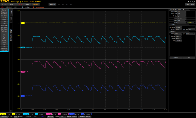
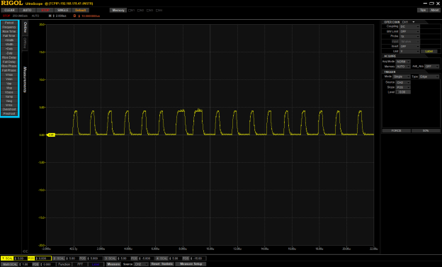
Thinking about this, it was like there was some capacitance that was not completely discharging. I went back to the schematic, this time looking at the piece that drive the data lines. The data sheet of the Shift Register indicated when disabled, the output lines are in a tri-state. I interpreted this that I would be best to tie these lines low. Just as a rule of thumb, I added 10kΩ pull down resistors on each of the output lines. Meanwhile the implementation notes for the NeoPixels recommended a 470Ω in series with the data line. I figured this is what was slowing down the signal. I decided to, first of all, replace the 470Ω with a zero Ohm resistor. There was a noticeable improvement but it still was not reaching the zero level and the logic analyser was not able to pick up the change. I then changed the 10kΩ to 4k7Ω. The result was again the same; clear improvement but not quite there. I then changed the 4k7Ω to 1kΩ and voila! The signal looked good, the Logic Analyser could detect the change in signal and best of all, the NeoPixel Strips reacted perfectly to the data sent down the lines. So my assumption seems to be confirmed that the resistors were affecting the output (and or input) capacitance. The screenshot shows a good comparison of the before (channel 3) and after (channel 2).

Coding
With the electrical aspect operational, the fun starts with the firmware. I wanted to start to do things properly in terms of organising the code. Previously, I had paid more attention to just getting things working and not really bothered about modularity. This time I broke up the NeoPixel driver into neopixel.c and neopixel_anim.c I also broke out the code specific for the Shift Register into attiny1614_sr595.c and attiny1614_sr595.h. Now the main.c had no direct dependency on the Shift Register module.
It still requires more work to enable the GPIO to be more configurable, but the major part of the API allows the caller to specify what data should be written to the respective “Channels”. I have other library routines to fill or manipulate the buffers in some way. The example below shows how three strips could be configured to display a “Rainbow Chaser” where the two outer strips, initalised with two colours only, are five pixels out of phase and the inner, initialsed with six colours, is running in the opposite direction.
#include
 #include "neopixel.h"
 #include "neopixel_anim.h"

/*! The setting for the CLKCTRL.MCLKCTRLB register */
 #define _MAIN_CLOCK 0x00
 #define BASE_HUE 0x03

uint8_t buffer[3][neopixel_buffer_size];

int main(void)
 {
 // This register is protected and can not be changed until the

// CPP register in the CPU is written with the signature of

// 0xD8

// This PEN flag is reset, this means that the Source clock is

// fed right through and not pre-scaled.

CPU_CCP = CCP_IOREG_gc;
 CLKCTRL.MCLKCTRLB = _MAIN_CLOCK;

// initialise the GPIO

neopixel_init();

uint8_t c1[] = { 0x04, 0x00, 0x00 };
 uint8_t c2[] = { 0x00, 0x02, 0x00 };

// initialise the buffers with the basic colours

neopixel_anim_init_bicolor(buffer[0], c1, c2);
 neopixel_anim_init_rainbow(buffer[1], BASE_HUE);
 neopixel_anim_init_bicolor(buffer[2], c1, c2);

// Shift one buffer along five pixels

for(uint8_t i=0; i<5; i++){
 neopixel_shift(buffer[2], true);
 }

while(true){
 // write to channel 1.
 neopixel_setchannel((uint8_t)0b00000001);
 neopixel_show(buffer[0]);
 // Write to channel 2.
 neopixel_setchannel((uint8_t)0b00000010);
 neopixel_show(buffer[1]);
 // Write to channel 4.
 neopixel_setchannel((uint8_t)0b00000100);
 neopixel_show(buffer[2]);

// shift each buffer along one pixel.

neopixel_shift(buffer[0], true);
 neopixel_shift(buffer[1], false);
 neopixel_shift(buffer[2], true);

delay_ms(100);
 }

return 0;
 }
|
Conclusion
I have provided a small video of a collection of animations that showcase the control of the strips through the 74HC595 Shift Register. I try to highlight the possibility to share the buffer arrays that contain the colour information across multiple strips by writing to them in parallel.
I am still quite satisfied with the performance of the ATTiny1614 for this application. The Flash and RAM sizes of the microcontroller provided no obstacle for the animations I have created so far. It is clear, more memory would be required if all 8 lines were to be used and controlled by 8 buffer arrays. I did a quick check to see what the compiled RAM usage would be for 8 arrays. It came back with 70% usage. I would need to try this out to see if this would be a problem.
As always with these types of projects, there is always something else that could be added. One feature I have not yet added is the ability to write text on the strips. It should be possible but 5 strips is too few to create reasonable, consistent characters. This would also require the creation of some type of font metadata. These could subject to a future project.

What clock speed are you running this at? I had considerable difficulties with timing on a WS2812-based project using 20 MHz ATtiny devices. I needed to embed assembly language to make it reliable.
LikeLike
I am running it at 20MHz. I also had to embed assembly to get the level of control needed. I pasted my driver in my previous post.
LikeLike
I just started playing with WS2812B’s and saw an interesting challenge in getting a long string running on an Attiny85. I came up with a simple algorithm-based idea which doesn’t need 3 bytes of RAM to hold each pixel color. My code uses virtually no RAM for any length string. I posted a version to GitHub (https://github.com/bitbank2/NeoPixel) and am working on adding new features/algorithms. I was able to drive the WS2812B’s without using assembly language on a 16Mhz Digispark ATtiny85.
LikeLiked by 1 person
This is a neat idea. I had started thinking about how to do something similar. I was also thinking about compressing down the colour information such to use only two to four bits for each colour since I was not actually ever using the full eight bits.
LikeLike