
I became interested in a LED display I saw in a beer garden over Summer. The remarkable thing was that it was clearly LEDs on a bus of only two wires. Even so the LEDs were able to be animated such that they could blink in unison or every other alternatively. I was intrigued as to how this could be done.
The purpose of this project was to come up with a means to to alternately blink a chain of LEDs either in unison or alternately using only two wires. During the development, what I had not realised until quite late was, I was actually using a H-Bridge
The Idea
I deduced that the LEDs must be connected to the bus in alternate directions. I also observed that there is probably some persistence of vision in use to give the illusion that the LEDs are all on at the same time. So basically I need a way to power alternatively connected LEDs on a two wire bus.

Design
I attempted this over several phases to demonstrate how this could be done. The first was to model a proposed circuit in Falstad/circuit. This allowed me to verify the basic operation of the circuit. I realised that a J-K Flip-Flop would be ideal for controlling the base/gates of the transistor or FET.

The second approach was to build the circuit on a breadboard, with parts that already have available. To this end, I did not have any through-hole N-Channel FETs but I did have some 2N3904 NPN transistors. Here, I could verify the basic principle of operation.
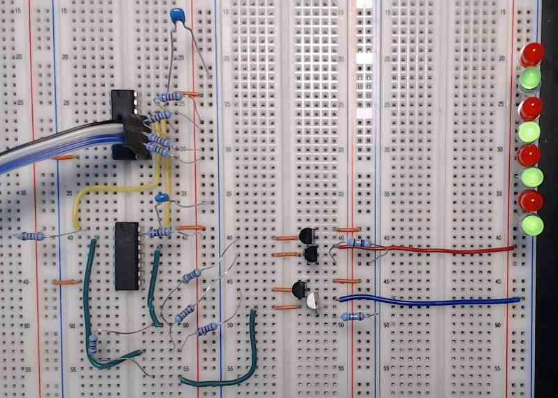
I used a CD4027 J-K Flip-Flop and used a Function Generator to provide the clock signal to the J-K Flip-Flop. There I could clearly see the persistence of vision in operation from about 100 Hz
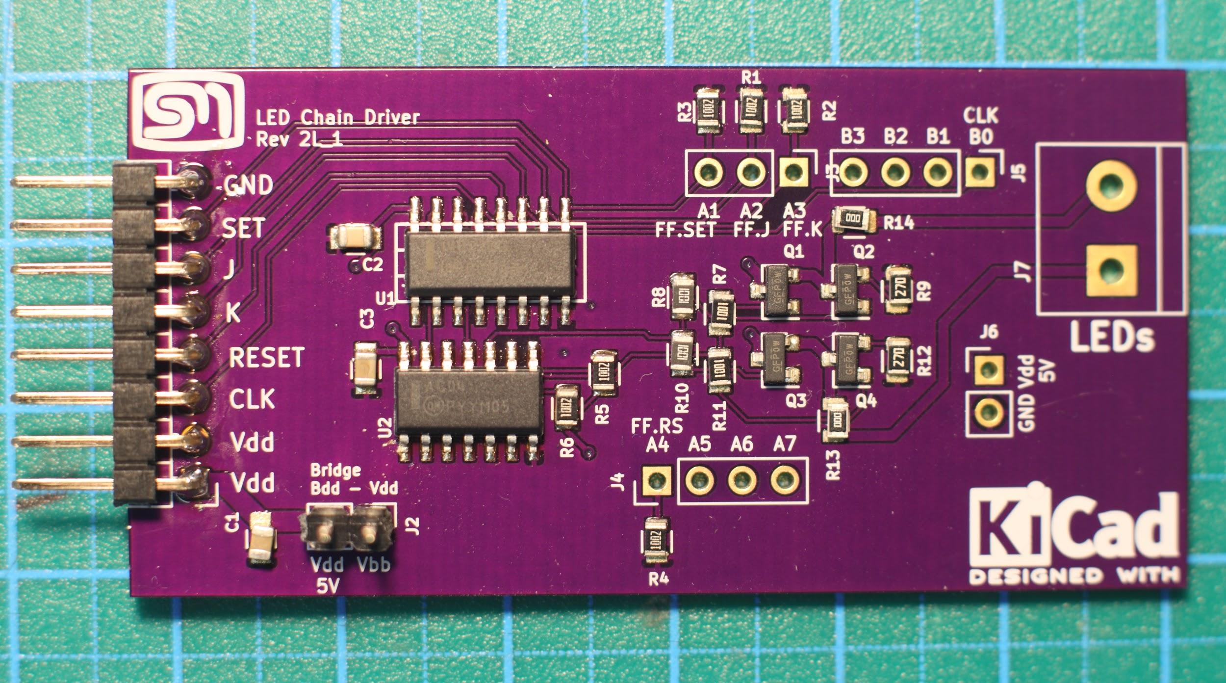
Finally, I was able to take the proven circuit and create a custom board. I had to experiment a bit with working out how to solder the 0805 SMD LEDs onto the enamelled wire.
I was concerned about the current through the resistors. I was thinking that the current should be limited to a maximum of 10 mA. The LEDs in use have a voltage drop of 1.83 V. Since the the LEDs are all in parallel, it was assumed that the total current drawn would be 10 mA ✕ n LEDs. i.e. For 10 LEDs, this would come to an expected a maximum current draw of 50 mA – 5 LEDs on each bank. Only one bank is ever active at one time.
Results
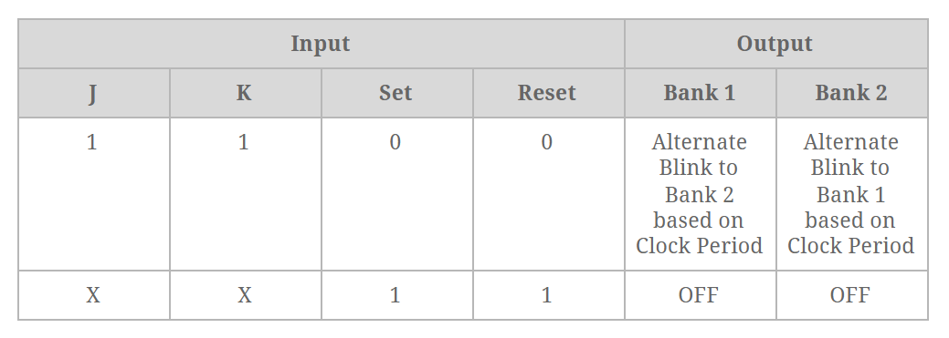
The design worked well at each phase and I had no issues with the resulting board. One aspect I needed to change in the design was to place an inverter on the Q and Q-bar outputs. This prevents both banks of transistors from being turned on at the same time. If this were allowed to happen then the current would bypass the LEDs and flow directly through the current limiting resistors. The truth table for the 4027 J-K Flip-Flop shows that both Q and Q-Bar are possible when both SET and RESET are high. The up-shot of adding an inverter means that when SET and RESET are high, both banks of LEDs are in an off state.
Activating all LEDs is achieved through Persistence of Vision by alternating the two banks of LEDs at about 100Hz. It was found that more than this was not necessary.

The behaviour of the LEDs could be influenced by manipulating the J, K , SET and RESET pins as shown in Table 1.

While waiting for the board to arrive, an invite arrived from a local Maker Space to enter in a “Gingerbread House” make competition. The panels were made from laser cut plywood. For this, I merely translated the breadboard configuration over to a prototyping board that was modelled the same as a breadboard.

Soldering the LEDs to the enamelled wire was a challenge. The simplest approach was to lay out the wire in parallel and scrape the enamel with a scalpel, tin the scored area and then attempt to solder the LED in place. I won’t say it was easy but with a bit of practice it seemed to work OK. The connections were not the greatest but once the LEDs were hot-glued to the holding frame it became much more stable.
Conclusion
The whole approach worked well and I was able to simulate the animations I had observed in the LED chain that inspired this project. What I did not realise however, is that this is a known configuration. I probably should have been aware of this but it was brought to my attention that this configuration is what is called a H-Bridge – commonly used in motor controllers.
Another aspect that might be worth further investigation is the current draw. This was significantly less than what I had anticipated. I found that in order to get a reasonable brightness out of the LEDs, I had to reduce the current limiting resistor even further that what I had calculated. One thought is to examine the effect of the alternate blinking which is essentially a PWM signal. This might be impacting the actual current being drawn.
What was particularly rewarding was to get this project working in a proper setting and not just on the lab desk. A friend took care of the making and painting up the gingerbread house and I installed the lighting. It managed to get an even first place!
What I learned
Like any project, there are problems along the way that need to be solved and aspects of working with micro-controllers that I have not yet been exposed to or I have not explored these areas very deeply.
- Using the function generator to test a circuit. This was particularly useful in being able to set up a constant signal into the J-K Flip-Flop and then manually manipulate the J, K, SET and RESET pins to study their effect first hand.
- Atmel ATTiny processors have a series of timers that have mixed functions and capabilities. These are named TCA, TCB, TCD and the Real-Time clock RTC. The TCA type timer was used to generate the 100 Hz signal for the JK Flip-Flop clock input signal. The RTC was used to generate a one second interrupt to coordinate the timing and selection of the various animations for the display.
- Next time I decide to add a micro-controller to a board and break out the unused pins, I should always include the power rail too. The board I used as a quick micro to add was a board I did a while back to experiment with driving some Neo Pixels. I had exposed the unused pins with the idea that I might use this board some other time.

One thought on “Bidirectional LED Driver”