
I have looked into using Neo-pixels strips and I was really impressed with the simplicity of use. Now I was curious about controlling a matrix of individual, non-addressable RGB LEDs. So I searched out a LED Matrix driver that looked like it could handle RGB LEDs. My search ended with the IS31FL3736 12×8 DOTS MATRIX LED DRIVER WITH INDIVIDUAL AUTO BREATH FUNCTION. This seemed to have the features I wanted to start out with and did not require me to install masses of LEDs. This is a note about what I learned along the way.
Goal
The goal of this project is to understand how to control a matrix of RGB LEDs using a dedicated driver and to find out what is involved in using one of these drivers in a design and what new concepts need to be learned.
Method
Choosing the Driver
The first place is to choose a driver. I did some searching around but my criteria was really not well defined since this was my first attempt to look at such things. The main criteria was
- Simple to use
- Able to support RGB
- Able to support a reasonable number of LEDs
- Interface with IIC
I say that it should support a reasonable amount of LEDs but I did not want a large number for the first attempt. I would need to at least hand place them and at worst solder them all.
A quick search and I settled for the IS31FL3736 . It could support 96 individual LEDs or 32 RGB LEDs. It has an additional feature I had not heard of before but thought would be interesting – Auto Breath Mode (ABM). I realised by the name what this would mean – that the device could control the LEDs with a varying Pulse Width Modulated (PWM) signal and create that breathing or pulsating effect that you see often in consumer products.
Schematic and Design
I now needed a board. A development board is available from ISSI, but I wanted to create my own. For the schematic, I simply used the reference design in the datasheet. I resisted adding a micro controller in the design as I would normally do. I decided to keep this project generic and open for other uses. So I could attach this to any other micro controller supporting the IIC interface. In this case I simply exposed all the communication pins and also set them up so that I could chain several of these boards together i.e. on a ribbon cable as a bus.
The chip supported two power domains. One for the LED matrix (Vcc) and another for control and IO (Vio). This means that the load could be driven with 5 volts and still be compatible with a micro controller that can only support lower voltages i.e. 3.3V.
The device can be configured for one of 16 IIC addresses. So I needed a way to set the address. I made this as flexible as possible by leaving the IIC addresses open and installed a set of solder-jumper connections. This way I could manually choose the address for each subsequent board.

I set up the matrix as given in the application notes of the datasheet. Assigning each “switch” channel a LED colour. This became four rows by eight columns of RGB LEDs but still 96 LEDs in all – but I would only be installing 32 RGB LEDs.

The Layout
The IS31FL3736 is a QFN package. This was going to be a challenge as I have not had a lot of experience with these packages and I have to admit, I avoid them as much as possible. Even with this tight pitch, I did not let that put me off. I went for a two layer board and made the LED section break away from the control section so that I could plug one section on top of the other, if I so wished. I took advantage of OSHPark’s After Dark (Black Substrate and Clear Mask) option. I thought if this little project was successful, I might want to use it somewhere else and so black background might be useful.
Since I had space, and so I did not keep going back to the datasheet, I added the IIC address reference table to the layout.

Assembly
The assembly went well. Since I was using a part with such a tight pitch, I ordered a set of stencils to apply the solder paste. I used a solder mask clearance of 0. I was thinking afterwards (i.e. after applying the solder paste) if I should have set a clearance to reduce the amount of solder to be applied. But in the end, I was very impressed that the reflow process went well. I only had minimal bridging on a couple of pins of the IS31FL3736 that was easy to clean up.


Powering Up
I was concerned that the QFN would give me some issues since the amount of solder paste did seem rather a lot. But I was satisfied that I had no shorts and the system seemed to come up OK. As is my usual approach, I took things slowly. Powering up the board on its own, then attaching the LED section and then powering up again. Satisfied there were no shorts, the next stage was to see if I could communicate with the device and then build up the firmware.
Firmware
Now that I did not limit myself to a particular micro controller from the start, I was open to choose any device I had available. For this I chose a Teensy LC only because it was close at hand. Since I am open to try out different things, I thought to give Platform.IO a turn within the Atom editor.
It took a little while to get the IIC interface correct but once that was done, then things started to work nicely. I first built up some simple examples i.e. single colours at first and then expanded. I probably should have used the time to build a library but I was focused on immediate results and not the long term at the moment.
With each iteration of the firmware examples, I added to the complexity
- Single colour.
- Single colour animation patterns.
- Rainbow transition – using PWM.
- Rainbow transition – using ABM.
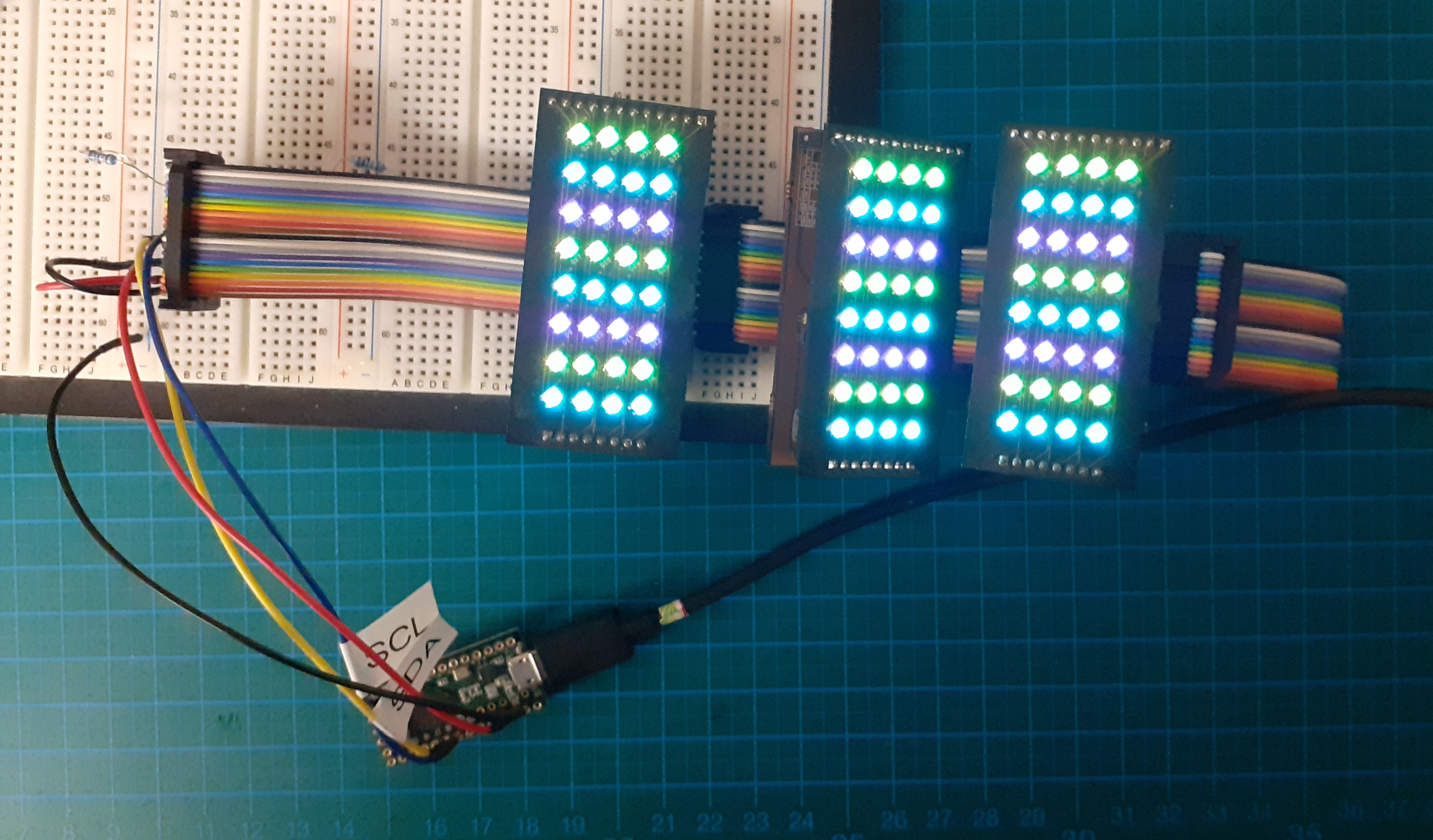
- Multiple boards connected together.
The device contains three timers and the rise and decay of the ABM signal can be configured with these timers. Where the rainbow transaction required 100% dedication from the micro controller, using the ABM and timer configuration it is possible to set up a pseudo rainbow transition with no involvement from the micro controller.
Using the PWM, I could control the phasing exactly how I wanted to create the effect I needed to produce a rainbow transition – where the colours are evenly spaced in time.


Using the ABM with the provided timers and configuration, the above pattern was not so easy to produce. There are three timers. Each timer can set up the PWM signal with four parameters that they refer to as T1 to T4. Each of these timers can also be configured to start their loop (Loop Begin time) at a particular position of the PWM signal i.e. Loop Begin from either T1, T2, T3 or T4. This causes an interesting issue when attempting to create an even rainbow transition.
Since each of the three phases (RGB) can only start on the beginning of one of the four timings, there is a gap in the rendering of one of the RGB colours. In the depiction below, it can be seen that there is never a Red LED on its own. It is always with a mix of Green and Blue. This issue was evident when I tried to create a rainbow-transition chaser effect so that the rainbow would ripple across the matrix. There it could be seen that certain colours would simply skip a row (or column depending on the direction).

The best workaround I have yet found for this is to basically set the peak section of the signal to 0 seconds i.e. T2=0. This gives the signal a type of saw-tooth appearance. Thereby, the RGB colours do come through, albeit rather short. In this case yellow and magenta fail to be rendered.

Conclusion
There is always something satisfying about getting something to blink. The satisfaction is increased when it is in different colours. The IS31FL3736 was an interesting device and I found it was a reasonable place to start. I came to understand more about what these devices can be capable of and how flexible they can be to control individual or groups of LEDs. It could well be that I have missed something in the setup of the ABM to achieve a smoother and even rainbow transition.
 There is still a lot to learn about using these types of devices, especially when it comes to creating more sophisticated animation effects or even to render text on the matrix display. Before I go that far I would need to clean up the code that I have created to organise it as a type of library with perhaps utility functions to assist with some of these more advanced ideas.
I have now gained a bit more insight into these devices and would consider using such a device for a project that required some type of dynamic lighting effect.
